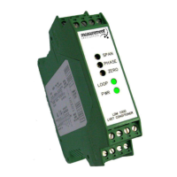
LDM-1000
LVDT/RVDT Signal Conditioning Module
TE CONNECTIVITY SENSORS /// LDM-1000 OPERATION MANUAL P/N 09290100-000 REV. C 05/2016
Table of Contents
1. Introduction ......................................................................................................................................................3
2. Product Specifications ....................................................................................................................................3
3. Product Description .........................................................................................................................................4
4. Initial Setup Procedure ....................................................................................................................................4
4. 1. Supply Voltage .............................................................................................................................................5
4. 2. Internal Switches ..........................................................................................................................................6
4. 3. Oscillator Frequency: ...................................................................................................................................6
4. 4. Oscillator ‘Sync’ Mode ..................................................................................................................................7
4. 5. Oscillator Drive Capability ............................................................................................................................7
4. 6. Setting the Amplifier Gain ............................................................................................................................7
5. Dimensions and Wiring Terminals .................................................................................................................8
6. Connection Diagrams ......................................................................................................................................9
7. Calibration Procedure .................................................................................................................................. 10