LDM-1000
LVDT/RVDT Signal Conditioning Module
TE CONNECTIVITY SENSORS /// LDM-1000 OPERATION MANUAL P/N 09290100-000 REV. C 05/2016
3. Product Description
DIP switches are provided to allow selection of three transducer excitation frequencies (2.5, 5 and 10 kHz), two signal bandwidths
(250 or 1,000 Hertz), and two excitation voltages (1 or 3 Volts RMS). Switches are also provided to select seven coarse gain
ranges, three DC output voltage ranges, two offsets, and master/slave operation. The 4 to 20mA output will operate regardless
of the DC output voltage dip switch settings.
Three multi-turn potentiometers located on the front panel allow precise gain (SPAN), offset (ZERO) and phase shift (PHASE)
adjustments.
An internal jumper allows changing the input voltage range from 18~30 VDC to 10~18 VDC.
A green LED on the front panel lights up when the LDM-1000 is powered on. A second green LED light indicates that the loop
current is flowing.
The LDM-1000 is designed to be mounted to a standard number 3 DIN rail. Input/output connections are made through plug-in
screw terminal barrier strips. These plug-in strips are keyed to prevent improper connections in the unlikely event that the LDM-
1000 should require field replacement.
The next few pages will take you, step by step, through the simple set-up and calibration process. This device may be set-up for
several different full scale analog outputs; some of the potential configurations are listed below:
±5 VDC output
0 to 5 VDC output
0 to 10 VDC output
4 to 20mA DC output
Standalone and Master/Slave operation
4. Initial Setup Procedure
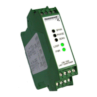
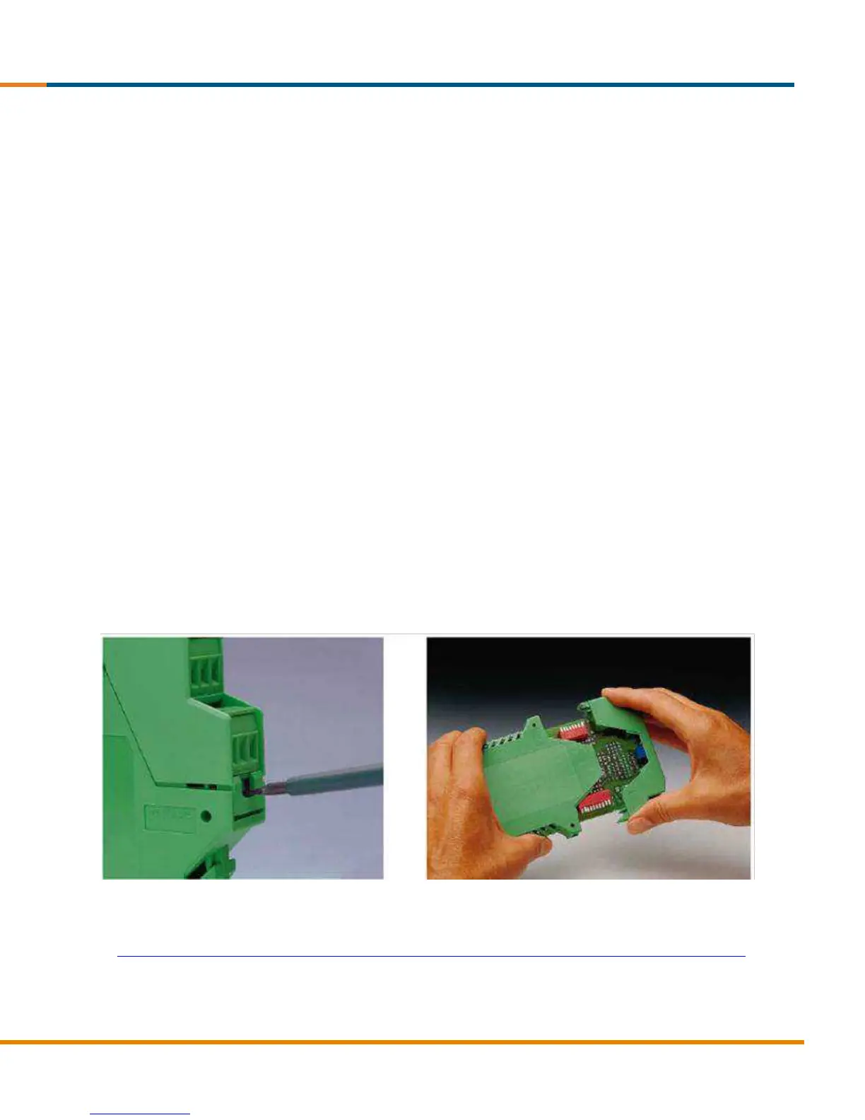
To properly configure the LDM-1000 for the LVDT or RVDT you are using, you must access the internal dip switches. To open
the housing, depress the two latches with a screwdriver (see photos below); the housing will spring open. You can slide the front
panel and PC board assembly forward approximately 1.6 inch (4cm) to access the dip switches and input voltage jumper. A
spring stop prevents the PCB from being removed completely.
In order to begin the setup process, you must first know a few basic characteristics about the LVDT or RVDT you intend to use
with the LDM-1000. The information may be obtained from the transducer calibration sheet, catalog literature, or the TE web
site at:
http://www.te.com/usa-en/products/sensors/position-sensors/linear-position-sensors-lvdt-lvit.html?tab=pgp-story