LDM-1000
LVDT/RVDT Signal Conditioning Module
TE CONNECTIVITY SENSORS /// LDM-1000 OPERATION MANUAL P/N 09290100-000 REV. C 05/2016
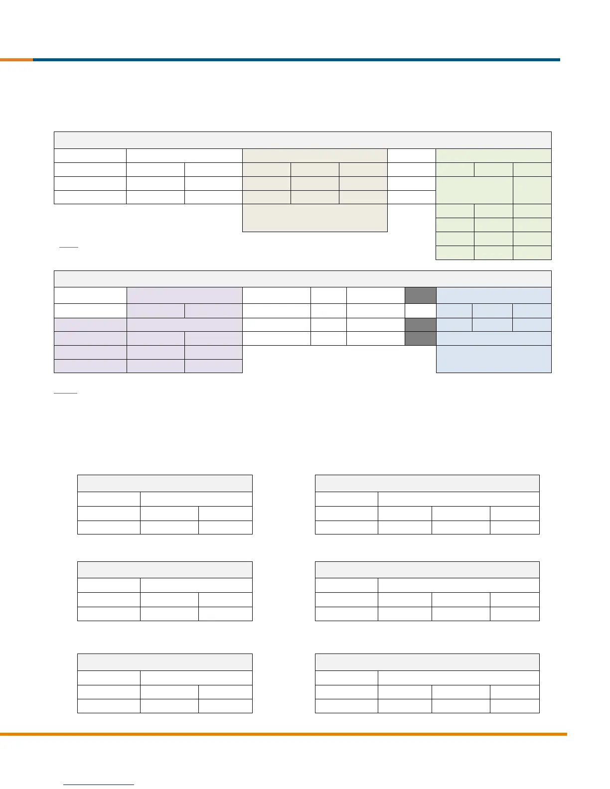
4. 2. Internal Switches
There are two internal DIP switch sets (SW1 and SW2) on the PC board assembly of the LDM-1000. The tables below explain
the switch positions and functions.
Note: Switches 3, 4 & 5 must be
in same position
Note: The 1 kHz bandwidth setting is not recommended for excitation frequencies other than
10 kHz, otherwise significant noise will be present on the output signal.
4 to 20mA output works
with any setting
Notes: Default factory settings are noted in BLUE in the above tables. Switch No. 5 of SW2 is not used. 3VRMS excitation is
available only with the 18~30VDC supply voltage setting.
4. 3. Oscillator Frequency:
Once you have established the proper excitation frequency for your transducer, refer to the tables below to set the oscillator.
For 2.5 KHz excitation (default factory setting):
For 5 KHz excitation:
For 10 KHz excitation: