EasyManua.ls Logo

Teac A-3300SR - Adjustment Sequence Chart; Power Supply Check and Adjustment; Playback Head Azimuth Adjustment

Teac A-3300SR
58 pages
Print Icon
To Next Page IconTo Next Page
To Previous Page IconTo Previous Page
Loading...
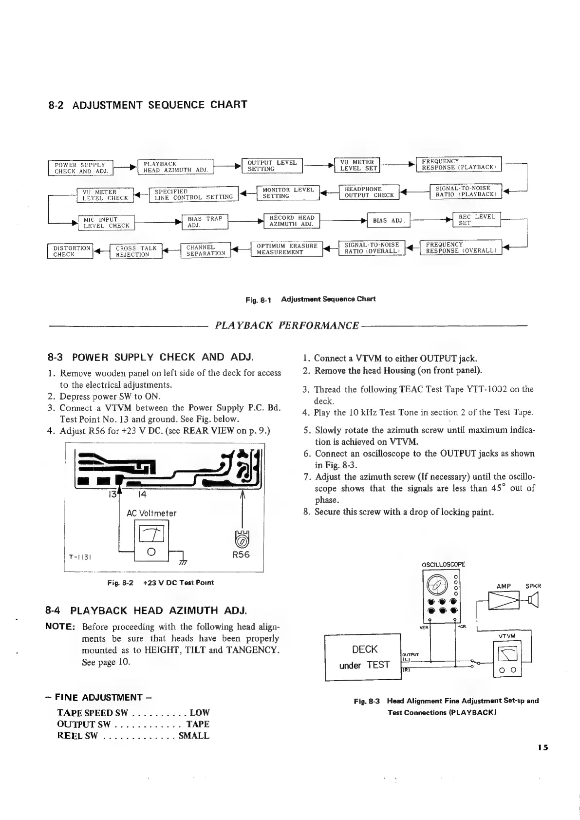
8-2.
ADJUSTMENT
SEQUENCE
CHART
y
>
PLAYBACK
>
OUTPUT
LEVEL
eons
NRE
AD
z
HEAD
AZIMUTH
ADJ.
SETTING
CHECK
AND
ADJ
VU
METER
SPECIFIED
LEVEL
CHECK
LINE
CONTROL
SETTING
MONITOR
LEVEL
SETTING
>
VU
METER
>
FREQUENCY
LEVEL
SET
RESPONSE
(PLAYBACK?!
HEADPHONE
OUTPUT
CHECK
RATIO
(PLAYBACK)
|
MIC
INPUT
LEVEL CHECK
BIAS
TRAP
ADJ.
RECORD
HEAD
AZIMUTH
ADJ.
OPTIMUM
ERAS
MEASUREMENT
URE
SIGNAL-TO-NOISE
FREQUENCY
[_RATIO
(OVERALL)
RESPONSE
(OVERALL)
SIGNAL-TO-NOISE
REC
LEVEL
DISTORTION
CROSS
TALK
CHANNEL
CHECK
REJECTION
SEPARATION
Fig.
8-1
Adjustment
Sequence
Chart
—
—_——
PLAYBACK
PERFORMANCE
8-3
POWER
SUPPLY
CHECK
AND
ADJ.
1.
Remove
wooden
panel
on
left
side
of
the
deck
for
access
to
the
electrical
adjustments.
2.
Depress
power
SW
to
ON.
3.
Connect
a
VITVM
between
the
Power
Supply
P.C.
Bd.
Test
Point
No.
13
and
ground.
See
Fig.
below.
4.
Adjust
R56
for
+23
V
DC.
(see
REAR
VIEW
on
p.
9.)
=—n_
7
AC
Voltmeter
:
R56
|
+23
V
DC
Test
Point
T~HISI
Fig.
8-2
8-4
PLAYBACK
HEAD
AZIMUTH
ADJ.
NOTE:
Before
proceeding
with
the
following
head
align-
ments
be
sure
that
heads
have
been
properly
mounted
as
to
HEIGHT,
TILT
and
TANGENCY.
See
page
10.
—
FINE
ADJUSTMENT
—
TAPE
SPEEDSW
..........
LOW
OUTPUT
SW
............
TAPE
REEL
SW
.............
SMALL
.
Connect
a
VTVM
to
either
OUTPUT
jack.
.
Remove
the
head
Housing
(on
front
panel).
.
Thread
the
following
TEAC
Test
Tape
YTT-1002
on
the
deck.
.
Play
the
10
kHz
Test
Tone
in
section
2
of
the
Test
Tape.
.
Slowly
rotate
the
azimuth
screw
until
maximum
indica-
tion
is
achieved
on
VITVM.
.
Connect
an
oscilloscope
to
the
OUTPUT
jacks
as
shown
in
Fig.
8-3.
.
Adjust
the
azimuth
screw
(If
necessary)
until
the
oscillo-
scope
shows
that
the
signals
are
less
than
45°
out
of
phase.
.
Secure
this
screw
with
a
drop
of
locking
paint.
OSCILLOSCOPE
under
TEST
Fig.
8-3
Head
Alignment
Fine
Adjustment
Set-up
and
Test
Connections
(PLAYBACK)
15