Do you have a question about the Teac A-2300SR and is the answer not in the manual?
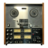
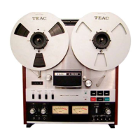
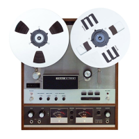
Technical specifications and service data for the TEAC A-3300SR tape deck model.
Mechanical service data including tape speed deviation, wow/flutter, and reel torque for tape decks.
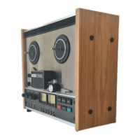
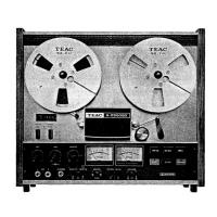
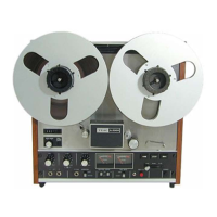
Technical specifications and service data for the TEAC A-2300SR tape deck model.
Electrical service data covering frequency response, signal-to-noise, and distortion for tape decks.
Instructions for disassembling the wooden sides and rear panel of the tape deck.
Step-by-step guide for removing the head assembly from the tape deck.
Procedure for removing the capstan motor from the tape deck unit.
Detailed steps for removing the capstan assembly from the tape deck.
Instructions on how to remove the reel motor from the tape deck.
Steps for removing the left and right tension arms of the tape deck.
Identification of tape transport parts visible from the rear view.
Instructions for replacing and wiring tape heads on the unit.
Identifying the screws and nuts used for head adjustment.
Method for performing visual alignment of the tape heads.
Procedure for measuring and adjusting pinch roller pressure.
Steps for measuring and adjusting the brake torque.
Procedure for measuring take-up torque on tape reels.
Method for measuring back tension during tape playback.
Method for checking tape speed accuracy using a test tone.
Procedure for measuring tape wow and flutter.
Instructions for converting voltage and frequency settings for export models.
Diagram showing locations for electrical adjustments on PC boards.
Flowchart outlining the sequence for electrical adjustments.
Procedure for checking and adjusting the power supply voltage.
Steps for adjusting the azimuth of the playback head.
Guide for setting the output audio levels for the tape deck.
Procedure for calibrating the VU meters to the correct level.
Steps to adjust and verify playback frequency response.
Procedure for measuring the signal-to-noise ratio during playback.
Instructions for setting the monitor audio levels.
Guide for setting the line input and output controls.
Verification of VU meter readings against specifications.
Procedure for checking the microphone input signal levels.
Procedure for checking the headphone output levels.
Steps for adjusting the bias trap circuit.
Procedure for adjusting the azimuth of the record head.
Steps for adjusting the bias level for optimal recording.
Procedure for setting the record input signal level.
Measurement and adjustment of the overall frequency response.
Measurement of the overall signal-to-noise ratio.
Procedure to measure the optimum tape erasure efficiency.
Method for measuring channel separation.
Procedure for measuring track-to-track cross talk.
Method for checking total harmonic distortion.
Instructions for cleaning heads, pinch roller, and tape guides.
Guidance on lubrication points and frequency for tape decks.
Information on specialized TEAC fluids for maintenance.
Procedure for demagnetizing record and playback heads.
Important notes and requirements when ordering spare parts.
Exploded view diagram and parts list for the A-3300SR model.
Exploded view diagram and parts list for the A-2300SR model.
Exploded view diagram and parts list for the A-3300SR model.
Exploded view diagram and parts list for the A-2300SR model.
Exploded view diagram and parts list for both models.
Exploded view diagram and parts list for both models.
List of accessories included with the tape deck.
Schematic diagram for the EQ and MIC Amplifier PC board.
Schematic diagram for the Line and Phone Amplifier PC board.
Schematic diagram for the Record and Meter Amplifier PC board.
Schematic diagram for the Bias Oscillator PC board.
Schematic diagram for the Head Select PC board.
Schematic diagram for the Switch Mounting PC board.
Schematic diagram for the Control PC board.
Schematic diagram for the Sensing PC board.
Schematic diagram for the Power Supply PC board.
Schematic diagram for the Control Relay PC board.
Schematic diagram for the Reel Motor PC board.
Parts list for the EQ and MIC Amplifier PC board.
Parts list for the Line and Phone Amplifier PC board.
Parts list for the Record and Meter Amplifier PC board.
Parts list for the Bias Oscillator PC board.
Parts list for the Head Select PC board.
Parts list for the Switch Mounting PC board.
Parts list for the Control PC board.
Parts list for the Sensing PC board.
Parts list for the Power Supply PC board.
Parts list for the Control Relay PC board.
Parts list for the Reel Motor PC board.
| Track System | 4-track, 2-channel stereo |
|---|---|
| Signal-to-Noise Ratio | 50 dB |
| Speed | 3.75 ips / 7.5 ips |
| Frequency Response | 30 Hz to 20 kHz |
| Wow and Flutter | 0.08% |
| Output | Line Level |