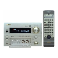
Do you have a question about the Teac AG-V8500 and is the answer not in the manual?
Notes on viewing PC boards, supplied parts, and component references within the manual.
Information on safety critical components and required replacement procedures.
Details on output power, distortion, frequency response, and tone control for the amplifier.
Specifications for FM and AM tuner sensitivity, distortion, and frequency response.
Video input/output specs, power requirements, consumption, and physical dimensions.
Required settings for AM and FM signal generators for optimal tuning and calibration.
Visual guide identifying component locations for tuning adjustments on the TUNER PCB.
Procedures for adjusting FM and AM frequency ranges and tracking circuits for accuracy.
Steps for adjusting FM mono distortion, stereo separation, and auto stop levels.
Visual breakdown of the unit's components for assembly and disassembly reference.
Comprehensive list of all replaceable parts with reference numbers and descriptions.
Internal wiring schematic specific to the USA/Canada version of the receiver.
Internal wiring schematic for Europe/UK model variations of the receiver.
Diagrams illustrating component placement on main, front, and tuner circuit boards.
Detailed circuit diagram for the front panel and its associated functions.
Detailed circuit diagram for the receiver's tuner section.
Detailed circuit diagrams for the main and power supply boards.
High-level overview of the receiver's internal signal flow and interconnections.