Do you have a question about the Teac CX-350 and is the answer not in the manual?
Detailed technical specifications of the cassette deck, including tape system, speed, inputs, and outputs.
Mechanical parameters such as tape speed deviation, wow and flutter, pinch roller pressure, and reel torque.
Electrical characteristics including frequency response, signal-to-noise ratio, and harmonic distortion.
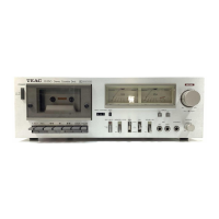
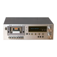
Technical drawing and dimensions of the cassette deck unit.
Diagram showing the internal layout of major components like the power transformer and PCB assemblies.
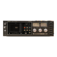
Diagram illustrating the location of front panel components such as heads, meters, and controls.
Procedure to check and adjust the capstan shaft thrust value.
Method for measuring and setting the pinch roller pressure.
Instructions for checking take-up and supply reel torque.
Procedure for setting and checking tape speed accuracy.
Steps to verify the proper operation of the muting switch.
Verification of the motor switch function during playback and stop modes.
How to adjust the lock plate release solenoid for correct operation.
Procedure for aligning the head azimuth for optimal playback.
Method for measuring and setting the output signal level.
Procedure to check the accuracy of the VU meters.
Checking the minimum input signal levels for MIC and LINE inputs.
Verifying the specific input level for the LINE input.
Procedure to check VU meter performance during monitoring.
Procedure for adjusting the bias trap for optimal recording.
Method to set the recording bias for different tape types.
Procedure for adjusting the recording input level.
Measurement of harmonic distortion during recording.
Procedure to check and adjust the frequency response during recording.
Measurement of signal-to-noise ratio during the recording process.
Procedure to check the tape erase efficiency.
Testing the REC MUTE function for proper operation.
Measurement of channel separation during recording.
Diagram showing test points on the REC/PLAY Amplifier Printed Circuit Board.
Table detailing various screw types, codes, and their descriptions for assembly.
An exploded diagram showing the external components and their assembly order.
List of accessories that are included with the cassette deck.
Exploded diagram illustrating the internal mechanism parts of the cassette deck.
Exploded diagram detailing parts of a specific mechanical sub-assembly.
Exploded diagram showing various electronic components and their mounting.
Detailed list of components for the REC/PLAY Amplifier Printed Circuit Board.
Detailed list of components for the Mechanism Printed Circuit Board.
The main circuit diagram illustrating the connections between various electronic components.
Important notes regarding component values, measurements, and safety critical parts.
| Brand | Teac |
|---|---|
| Model | CX-350 |
| Category | Cassette Player |
| Language | English |