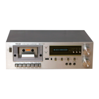
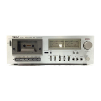
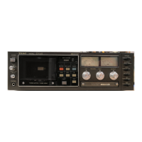
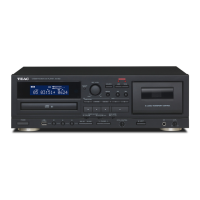
Do you have a question about the Teac CX-400 and is the answer not in the manual?
Detailed technical specifications for the cassette deck.
Technical data points for servicing and maintenance.
Adjusting the capstan shaft thrust value.
Measuring and adjusting pinch roller pressure.
Measuring and adjusting reel torque for tape movement.
Adjusting tape speed using a test tape.
Checking and adjusting the tension arm projection.
Lubrication points and recommended lubricants.
Procedure for converting voltage settings.
Adjusting the muting switch operation.
Adjusting motor switch for stop and rotation.
Adjusting pause switch position and clearance.
Checking rewind switch actuation.
Adjusting lock plate release solenoid position.
Important precautions before electrical adjustments.
Tests related to the recording performance of the deck.
Measuring signal-to-noise ratio for playback and record/playback.
Checking the efficiency of the erase head.
Testing the record mute function.
Measuring channel separation between tracks.
Checking crosstalk between adjacent tracks.
Evaluating the effect of the Dolby NR circuit.
Locations for adjustments and test points on PCBs.
Diagram showing exploded view of components.
Detailed list of all parts and their reference numbers.
List of accessories provided with the unit.
Diagram showing exploded view of components.
Coding system for hardware used in assembly.
Diagram showing exploded view of components.
Continuation of the detailed parts list.
Foil side view, component layout, and parts list for the main audio PCB.
Foil side view, component layout, and parts list for the power supply PCB.
Foil side view, component layout, and parts list for the meter amplifier PCB.
Lists for LED A, LED B, and VOLUME PCBs, and related components.
| Track System | 4-track, 2-channel stereo |
|---|---|
| Noise Reduction | Dolby B |
| Input | Line |
| Output | Line |
| Tape Type | Metal |
| Frequency Response (Normal Tape) | 30Hz |
| Frequency Response (Chrome Tape) | 30Hz to 16kHz |
| Frequency Response (Metal Tape) | 30Hz |
| Input Sensitivity/Impedance | 50kΩ |
| Power Supply | 220V, 50Hz |
| Type | Stereo Cassette Deck |