Do you have a question about the Teac C-1 and is the answer not in the manual?
Lists special tools and jigs required for servicing.
Details disassembly steps for the case and front panel.
Details disassembly steps for the tape transport chassis.
Procedure for adjusting the cassette holder timing.
Procedure for adjusting the head solenoid position.
Procedure for adjusting the capstan assembly thrust.
General notices and preparations for electrical checks.
Procedure for adjusting the +15V DC voltage.
Procedure for adjusting the record/playback head azimuth.
Procedure for setting the specified playback output level.
Checks for minimum input signal levels.
Calibration procedure for peak level meter indication.
Procedure for adjusting the bias trap circuits.
Procedure for setting the record bias.
Procedure for checking overall frequency response.
Procedure for checking erase efficiency.
Procedure for setting the voltage selector.
Description of the system control LSI.
Details input/output conditions and terminals of the LSI.
Explanation of tape deck operation and signal priorities.
Description of the initial power reset circuit.
Explanation of the solenoid drive circuits.
Description of the tape loading circuit.
Details on fast forward and rewind operations.
Explanation of operation in Play mode.
Explanation of operation in Pause mode.
Overview of the amplifier section.
Description of the signal switching circuits.
Description of the playback equalizer amplifier.
Description of the playback line amplifier.
Description of the bias oscillator control circuit.
Description of the Dolby encoder circuit.
Provides exploded views and lists of parts.
| Track System | 4-track, 2-channel stereo |
|---|---|
| Tape Speed | 4.76 cm/s |
| Dimensions | 435 x 110 x 286mm |
| Weight | 4.8kg |
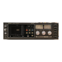
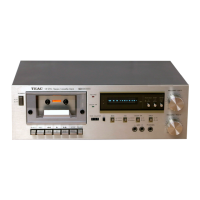
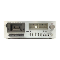
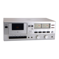
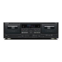
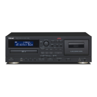
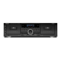
| Type | Cassette Deck |
| Tape Type | Metal |
| Signal-to-Noise Ratio | 52dB |
| Wow and Flutter | 0.05% (WRMS) |