Do you have a question about the Teac Esoteric R-9000 and is the answer not in the manual?
Details on track system and head configurations for R-9000/V-9000.
Information on tape type, speed, and winding time.
Wow/flutter, frequency response, S/N ratio, and input/output levels.
Power requirements, consumption, dimensions, and weight of the unit.
List of standard accessories provided with the unit.
Step-by-step guide for disassembling external components.
Diagram showing the location of various PCBs within the unit.
Procedure to measure and adjust pinch roller pressure.
Steps for adjusting tape path, including required tools.
Method for adjusting erase head height using specific jigs and tapes.
Adjusting record/playback head height and azimuth for optimal signal.
Erase head height adjustment procedure using jigs.
Tape path adjustment procedure.
Using jigs for head position and alignment.
Adjusting tape guide height using nut E.
Adjusting playback head azimuth with screw C.
Procedure for adjusting the photo sensor for tape detection.
Checking and adjusting reel torque with a cassette torque meter.
Adjusting tape speed using a frequency counter.
Measuring wow and flutter during playback.
Measuring wow and flutter during recording and playback.
Instructions for applying oil and grease to specific parts.
How to change the voltage selector for different regions.
Important precautions before performing electrical checks and adjustments.
List and purpose of TEAC test tapes used for calibration.
Locations for checks and adjustments on the Record/Playback Amplifier PCB.
Locations for checks and adjustments on the Control PCB.
Diagram showing test setup for azimuth adjustment.
Visual guide to confirming phase relationships.
Graph showing playback frequency response.
Setup for checking various test points on the unit.
Checking and adjusting head azimuth for optimal playback.
Measuring and setting Dolby playback level.
Checking playback output levels.
Setting the meter level for accurate readings.
Measuring playback frequency response.
Checking and adjusting the playback signal-to-noise ratio.
Testing minimum line input level.
Testing specified line input levels.
Testing input level for CD direct connection.
Checking meter level calibration.
Adjusting peak level meter readings.
Checking headphone output levels.
Testing the MPX filter function.
Checking the bias oscillator output.
Checking the step-up coil output.
Adjusting bias trap for recording.
Adjusting the built-in oscillator output.
Adjusting bias for recording (Test tape METAL).
Adjusting bias for recording (Test tape NORMAL).
Adjusting bias for recording (Test tape CrO2).
Setting and checking recording levels.
Measuring total harmonic distortion during recording.
Checking bias trap during playback.
Measuring overall frequency response in record/playback.
Measuring overall signal-to-noise ratio.
Checking built-in oscillator for bias and level.
Measuring erase efficiency.
Testing the REC MUTE function.
Measuring channel separation during recording.
Measuring crosstalk between adjacent tracks.
Adjusting CPS level for R-9000 model.
Adjusting CPS level for V-9000 model.
Checking the quick sensor function.
Block diagram for the CX20188 IC.
Block diagram for the CXA1198AP IC.
Block diagram for the BA6209 IC.
Block diagram for the BU4052B IC.
Block diagram for the M51143AL IC.
Block diagram for the M5230LA IC.
Block diagram for the LB1240 IC.
Block diagram for the LC7910 IC.
Block diagram for the L78LR05 IC.
Block diagram for the BA6800AS IC.
Notes regarding resistors, capacitors, and critical components.
Exploded view diagram of the R-9000 unit.
Continued exploded view of R-9000 unit with part numbers.
Second exploded view diagram of the R-9000 unit.
Continued exploded view of R-9000 unit with part numbers.
Continued exploded view of R-9000 unit with part numbers.
Third exploded view diagram of the R-9000 unit.
List of accessories included with the R-9000.
Exploded view diagram of the V-9000 unit.
Continued exploded view of V-9000 unit with part numbers.
Fifth exploded view diagram of the V-9000 unit.
Continued exploded view of V-9000 unit with part numbers.
Continued exploded view of V-9000 unit with part numbers.
Sixth exploded view diagram of the V-9000 unit.
Continued exploded view of V-9000 unit with part numbers.
List of accessories included with the V-9000.
Diagram of the Sensor PCB.
Diagram of a Joint PCB.
Diagram of the Switch PCB.
Diagram of the Cam PCB.
Diagram of another Joint PCB.
Diagram of the Record/Playback Amplifier PCB.
Diagram of the Record/Playback Sub PCB.
Diagram of the Volume/VR PCB.
Diagram of the Control PCB.
Diagram of the Front PCB.
Parts list for the Sensor PCB Assy (R-9000).
Parts list for the Switch PCB Assy (R-9000).
Parts list for the R/P Amp PCB Assy (R-9000).
Continued parts list for R/P Amp PCB Assy (R-9000).
Parts list for the R/P Sub PCB Assy (R-9000).
Parts list for the Control PCB Assy (R-9000).
Parts list for the VR PCB Assy (R-9000).
Continued parts list for Control PCB Assy (R-9000).
Parts list for the Front PCB Assy (R-9000).
Parts list for the Sensor PCB Assy (V-9000).
Parts list for the Switch PCB Assy (V-9000).
Parts list for the R/P Amp PCB Assy (V-9000).
Continued parts list for R/P Amp PCB Assy (V-9000).
Parts list for the R/P Sub PCB Assy (V-9000).
Parts list for the Control PCB Assy (V-9000).
Parts list for the VR PCB Assy (V-9000).
Continued parts list for Control PCB Assy (V-9000).
Parts list for the Front PCB Assy (V-9000).
| Brand | Teac |
|---|---|
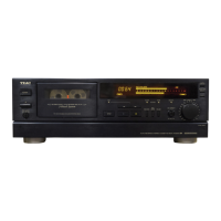
| Model | Esoteric R-9000 |
| Category | Cassette Player |
| Language | English |