EasyManua.ls Logo

Teac R-H300 - Playback Frequency Response; Bias Frequency Adjustment; Overall Gain Adjustment; Overall Frequency Response

Teac R-H300
15 pages
Print Icon
To Next Page IconTo Next Page
To Previous Page IconTo Previous Page
Loading...
Gerrits
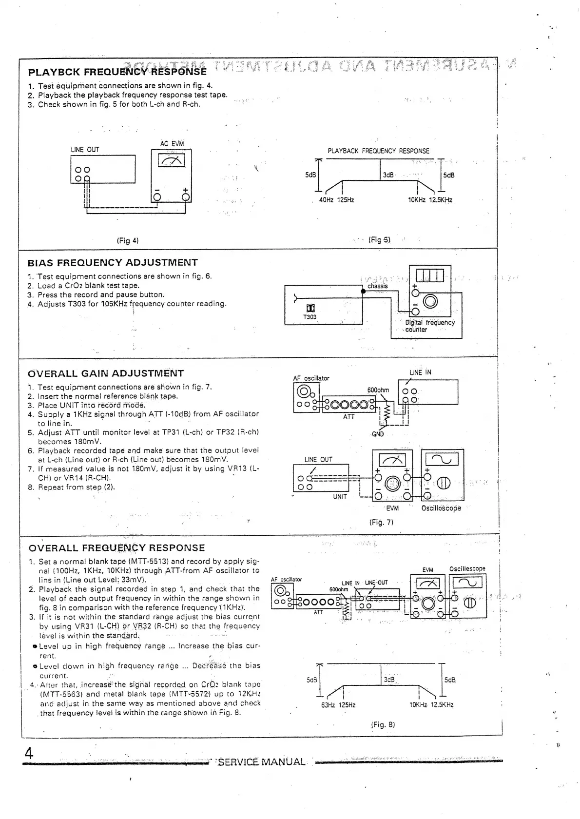
PLAYBCK
FREQUENCY-RESPONSE
|
*
1.
Test
equipment
connections
are
shown
in
fig.
4.
2.
Playback
the
playback
frequency
response
test
tape.
3.
Check
shown
in
fig.
5
for
both
L-ch
and
R-ch.
AC
EVM
LINE
OUT
=n
(Fig
4)
BIAS
FREQUENCY
ADJUSTMENT
1.
‘Test
equipment
connections
are
shown
in
fig.
6.
2.
Load
a
CrO2
blank
test
tape.
3.
Press
the
record
and
pause
button.
4.
Adjusts
T303
for
105KHz
frequency
counter
reading.
OVERALL
GAIN
ADJUSTMENT
PWN
oO
®Level
up
in
high
frequency
range
...
®
Level
down
in
—
frequency
range
...
a
.
Test
equipment
connections
are
shown
in
fig.
7.
.
Insert
the
normal
reference
blank
tape.
.
Place
UNIT
into
récord
mode.
.
Supply
a
1KHz
signal
through
ATT
(-
1008)
from
AF
oscillator
to
line
in.
.
Adjust
ATT
until
monitor
level
at
TP31
(L-
ae
or
TP32
(R-ch)
becomes
180mV.
.
Playback
recorded
tape
and
make
sure
that
the
output
level
at
L-ch
(Line
out)
or
R-ch
(Line
out)
becomes
180mV.
.
If
measured
value
is
not
180mV,
adjust
it
by
using.
VR13
(L-
CH)
or
VR14
(R-CH).
.
Repeat
from
step
(2).
OVERALL
FREQUENCY
RESPONSE
1.
Set
a
normal
blank
tape
(MTT-5513)
and
record
by
apply
sig-
nal
(100Hz,
1KHz,
10KHz)
through
ATT-from
AF
oscillator
to
lins
in
(Line
out
Level:
33mV).
.
Playback
the
signal
recorded
in
step
1,
and
check
that
the
level
of
each
output
frequency
in
within
the
range
shown
in
fig.
8
in
comparison
with
the
reference
frequency
(1KHz).
_
If
it
is
not
within
the
standard
range
adjust
the
bias
current
by
using
VR31
(L-CH)
or
VR32
(R-
ee
so
that.
the
|
eaneniey
level
is
within
the
standard:
:
neecene
bias
cur-
rent.
He
te
Decrease
the
bias
current,
Aiter
that,
increasé
the
signal
recorded
on
Cro:
blank
tape
(MTT-5563)
and
metal
blank
tape
(MTT-5572)
up
to
12KHz
and
adjust
in
the
same
way
as
mentioned
above
and
check
_that
frequency
level
is
within
the
range
shown
in
Fig.
8.
PLAYBACK
FREQUENCY
RESPONSE
5dB
5dB
1
I
_
40Hz
125Hz
10KHz
12.5KHz
chassis
§
{+
'
Digital
frequency
~
<Gounter
S
LINE
IN
AF
oscillator
EVM
6°
s(Oscilicscope
(Fig.
7)
EVM
Oscillescope
dB
ao
63Hz
125Hz
TOKH2
12.5KHz
(Fig.
8)
7
SERVICE
MANUAL.
"mimi
dee
ca
etnebnd
sn
railing