EasyManua.ls Logo

Teac TASCAM 32 - Page 6

Teac TASCAM 32
117 pages
Print Icon
To Next Page IconTo Next Page
To Previous Page IconTo Previous Page
Loading...
1.
Establish
the
record
active
condition
by
depressing
PLAY
and
RECORD
together,
then—
2.Depress
one
or
both
FUNCTION
select
buttons
and
recording
will
commence.
This
additional
logic
is
provided
when
it
is
necessary
to
hear
a
previously
recorded
signal
up
to
the
“punch-in”
point.
If
the
FUNCTION
select
buttons
are
OUT
(safe)
the
tape
signal
CAN
appear
at
the
output.
If
the
FUNCTION
buttonsare
IN
(record
ready)
only
new
INPUT
signal
can
be
auditioned
and
listening
to
the
tape
to
find
a
‘’Cue’’
point
for
the
punch-in
will
not
be
possible.
When
you
must
listen
to
the
tape,
pre-
load
the
record
logic
and
use
the
FUNCTION
buttons
to
begin
the
recording.
PAUSE
Button
This
button
will
stop
the
tape
and
the
recording
process
without
disengaging
the
record
logic,
to
continue
recording,
just
press
the
play
(>
})
button
alone.
If
a
RECORD/PAUSE
logic
condition
is
in
effect,
allowing
this
‘‘one
key’”’
return
to
record
mode,
the
green
and
red
LEDs
above
the
PAUSE
and
RECORD
buttons
will
light.
f
@
RECORD
Status
Indicator
The
red
LED
lights
up
when
the
deck
has
been
set
into
the
record
mode
and
begins
blinking
if
the
FUNCTION
buttons
are
not
depressed.
@
PAUSE
Status
Indicator
The
green
LED
lights
only
when
PAUSE
and
RECORD
have
been
simultaneously
pressed.
®
Shut
Off
Arm
The
shut
off
arm
will
drop
power
to
the
capstan
and
reel
motors
if
the
tape
breaks.
It’s
a
good
idea
to
allow
it
to
drop
when
you
take
a
break
in
the
middle
of
a
session.
Doing
this
will
stop
the
constant
rotation
of
the
capstan,
and
will
lengthen
the
life
of
the
capstan
motor
bearings.
It
is
not
necessary
to
unthread
the
tape.
Just
allow
it
to
become
slack
so
that
the
shut
off
arm
can
drop.
@
Pinch
Roller
@
Capstan
Shaft
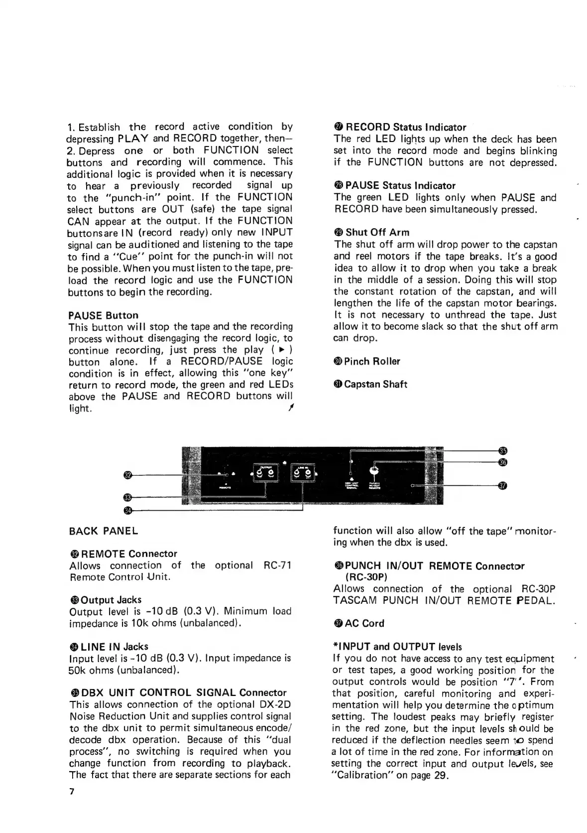
BACK
PANEL
@
REMOTE
Connector
Allows
connection
of
the
optional
RC-71
Remote
Control
Unit.
@®
Output
Jacks
Output
level
is
-10dB
(0.3
V).
Minimum
load
impedance
is
10k
ohms
(unbalanced).
@®
LINE
IN
Jacks
Input
level
is
-10
dB
(0.3
V).
Input
impedance
is
50k
ohms
(unbalanced).
@®DBX
UNIT
CONTROL
SIGNAL
Connector
This
allows
connection
of
the
optional
DX-2D
Noise
Reduction
Unit
and
supplies
control
signal
to
the
dbx
unit
to
permit
simultaneous
encode/
decode
dbx
operation.
Because
of
this
“dual
process’’,
no
switching
is
required
when
you
change
function
from
recording
to
playback.
The
fact
that
there
are
separate
sections
for
each
7
function
will
also
allow
“off
the
tape’
monitor-
ing
when
the
dbx
is
used.
@
PUNCH
IN/OUT
REMOTE
Connector
(RC-30P)
Allows
connection
of
the
optional
RC-30P
TASCAM
PUNCH
IN/OUT
REMOTE
PEDAL.
@
AC
Cord
*{|NPUT
and
OUTPUT
levels
If
you
do
not
have
access
to
any
test
equipment
or
test
tapes,
a
good
working
position
for
the
output
controls
would
be
position
“‘7'’.
From
that
position,
careful
monitoring
and
experi-
mentation
will
help
you
determine
the
optimum
setting.
The
loudest
peaks
may
briefly
register
in
the
red
zone,
but
the
input
levels
should
be
reduced
if
the
deflection
needles
seem
tO
spend
a
lot
of
time
in
the
red
zone.
For
information
on
setting
the
correct
input
and
output
levels,
see
“Calibration”
on
page
29.