Connection
Outputs are described in table 2. Configuration of inputs and
outputs can be made through built in menu – check "Menu 1".
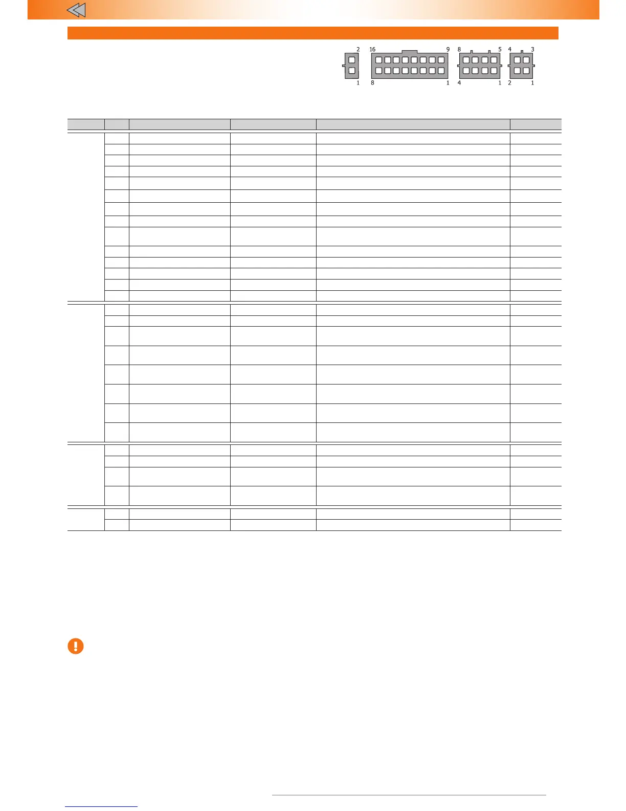
Рис. 1. Connector pin numeration from harness viewpoint
Table 2. Alarm connectors description
Connector # Colour Type Note Current, mA
16-pin
1, 2 – – – –
3 – – – –
4 Gray/black Input (–) Reference ground/Negative button 0,5
5 Pink/Green Programmable input (+) Stop signal control 1,5
6 Brown CAN Data bus CAN-L –
7 White/black Output (–) Wired engine lock 150
8 Black Power Ground –
*
9, 10 – – – –
11 Blue/red
Programmable
output(+/–)
Turn signals alternate control ±150
12 Gray/yellow Input (+) Analogue buttons/Positive button 0,5
13 Green/black Programmable input (–) Hood position control 1,5
14 Brown/red CAN Data bus CAN-H –
15 Pink/black Output (+/–) Siren Control (+)/H or n control(–) 1300/150
16 Red Power +12 V 1500/3,5
**
8-pin
1 Orange/green Programmable input (–) Disable alert if trunk is open 1,5
2 Orange/white Programmable input (+) Disable alert if trunk is open 1,5
3 Blue/yellow
Programmable
output (–)
Starter and diagnostic bus lock 50
4 Green/yellow
Programmable
output (–)
Time channel («Comfort») 50
5 Yellow/white
Programmable
output (–)
Front parking sensors control 150
6 Green/white
Programmable
output (–)
Rear parking sensors control 150
7 Green
Programmable
output (–)
Impulse to close hood lock 150
8 Blue
Programmable
output (–)
Impulse if PIN-code is entered 150
4-pin
1 Red/white Sensor power +12 V –
2 Black/yellow Sensor power Ground –
3 Gray/Blue Input (–)
Multiplex input #1 (Factory default)/
Sensor trigger input
–
4 Gray/Green Input (–)
Multiplex input #2 (Factory default)/
Sensor warning input
–
2-pin
1 Blue LED power Ground –
2 Red LED power +12 V –
*
Useful current of outputs depends on the load connected to negative outputs.
**
Current draw in idle and operation modes can change depending on current draw on
positive outputs.
Outputs #7, 11, 15 (16-pin connector) and outputs #3-8 (8-pin connector) are protected from short circuit,
inductive eruptions, overheating and maximum current surpassing.
16-pin connector description
Pin #3.
"Connection channel". Has to be connected to switched or non-
switched circuit of the vehicle. +12 V signal has to present in chosen
circuit if the engine is running. After installation please, check the link
between relay and the Alarm.
Please, do not connect "Connection channel" to the cigarette lighter
circuit.
Pins #4 and #12.
"Reference ground/Negative button" и "Analog
button/Positive button". Depending on chosen
control button type one of the following functions is used:
• "Negative button" and "Positive button" — connects though
any normally open non fixed buttons to the ground and +12V.
Used if there are no factory buttons "seen" by the alarm.
• "Analogue button" — connects to the wire at the spiral contact
at the steering wheel (check Integrator)
• "Reference ground" — connected if analogue button is selected
(check Integrator).
If the vehicle has buttons, controlled via CAN and avaliable to the
alarm, this inputs may not be used.