TEC-61157-1 Installation Manual-700/710 USB
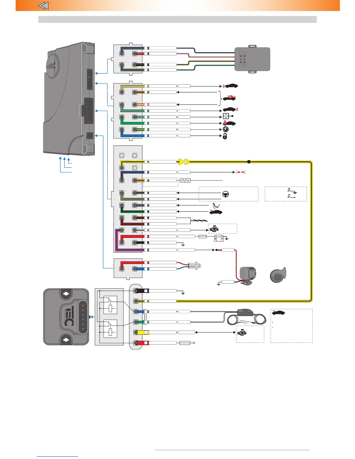
Connection scheme
LED
Mini-USB
Built-in
button
OUT (+)
Close hood lock
Open hood lock
OUT (+)
TEC 700 series
+12 V
Ground
LED
blue
red
Разъем Х4 (2-pin)
Х3
Х1
Х4
Х1 (16-pin)
Connection scheme for Slave-security system TEC 700 series
150 мА/1,5 mA
Probrammable IN (-)/OUT (-)
Underhood unit
HCU-230
6
2
3
4
5
1
Connect to the circuit with
non-switched +12 V voltage
7,5/15 А
*
10 А
10 А
TP-BUS – digital bus to control devices made by TEC electronics
Engine
lock factory
default
or
yellow
green
blue
red
black
Х2 (8-pin)
Disable alert if trunk is open
Impulse to close hood lock
Impulse after authentication
Rear parking sensors control
Programmable OUT (-)
Programmable IN (+)
150 mA
150 mA
Programmable OUT (-)
Programmable OUT (-)
150 mA
blue
Programmable OUT (-)
50 mA
Programmable OUT (-)
Starter motor and diagnostic
bus lock
Timer channel («Comfort»)
blue/yellow
50 mA
Front parking sensors
control
150 mA
Programmable OUT (-)
Programmable IN (-)
orange/green
orange/white
green/yellow
green
green/white
+12 V
Ground
Х3 (4-pin)
IN (-)
Х2
IN (+)
IN (-)
CAN-L
CAN
CAN-H
Connects to the can bus of the vehicle (check Integrator)
Programmable IN (-)
Hood position
Programmable IN (+)
Brake signals control
gray/black
pink/green
gray/yellow
green/black
brown/red
yellow/red
brown
For Prizrak 720/740
FSK-relay channel Connect to the circuit with non-switched +12 voltage
OUT (-)
Ground
150 mA
3А
12V
1500/3,5 mA
*
white/black
red
black
BRAKE
Wired
engine lock
or
Analog button
Connect
to the steering
wheel buttons
if required
Reference ground
Positive button
+12 V
Negative button
Analog buttons
Digital (discreet) buttons
*
Maximum current through normally open relay is limited by cross section of the wire (0,35 mm2). When transmitting (impulse) up to 1 A. When receiving up to 10 mA.
**
Do not install more than one FSK-relay
Relay works only as normally closed relay.
•
•
Engine will be locked when vehicle starts to move.
Movement information system recieves via CAN bus
If central unit was removed, relay will lock the engine
with built-in accelerometer (when vehicle starts to move).
•
•
FSK-relay pLine-221 (for Prizrak 720/740)
red/white
black/yellow
gray/blue
2
4
3
1
3
1
4
2
7
5
yellow/white
8
6
1
2
1300/150 mA
pink/black
15
*
Average current draw
in operation mode/
in idle mode
Programmable OUT (+/-)
with interchangable polarity Turn signals alternate control
blue/red
11
±150 mA
3
4
5
6
7
8
12
13
14
16
Hood
position control
Programm and connect if:
No hood position information
in CAN
Input «Hood position
control» is not connected
(Connector Х1 pin №13).
Check HCU-230 documentation
for programming procedure
Multiplex input №1
(Factory default)
Siren control (+)
(factory default)
OUT (+/-)
With interchangeble
polarity
red
black
or
Horn control (-)
IN (-)
Multiplex input №2
(Factory gray/green default)
gray/green
Optional
sensor
yellow/black
10
Underhood module HCU-230 control
yellow/black
Common pin
Normally open pin
Normally closed connection
FSK-relay connection and power
Connect to the circuit with switched current through 3A fuse.
Examples: ignition circuit, injetors, ignition coils e.t.c.
Yellow and yellow/black wires to lock
by cutting power circuit
Yellow and yellow/white (yellow/red)
wires to lock engine sensors.
Lock outputs:
•
•
«Ignition 1»
or
yellow/white
red
black
3 А
*
10 А
10 А
1 А/10 mA
*
*
On
yellow/red
yellow/black
yellow