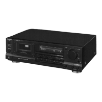
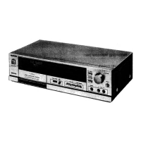
RS-B755
Mi
CONTENTS
Page
Page
SAFETY
PRECAUTION
.........cccsssscsssssnsneessssrsssetnensensenssensssesonare
2
PRINTED
CIRCUIT
BOARDG.............s:sssesesssssesssersescores
30~34
ACCESSORIES
WIRING
CONNECTION
DIAGRAM
...
FRONT
PANEL
CONTROLS
AND
FUNCTIONG...............
3,
4
REPLACEMENT
PARTS
LIST.......scssssssscssssesseensesstenseess
CONNECTIONS.
.......csscssscssesnecsssssneenesenesnsesnsesssssnsesnennesneraneconeans
EXPLODED
VIEWS.
......s.csscsssssnesnesnssnsententenecnssnesnseneensesys
RECORDING
WITH
HIGH
TONE
QUALITY
se
REPLACEMENT
PARTS
LIST.
DISASSEMBLY
INSTRUCTIONG..............::sssssssesssoeseessoees
RESISTORS
&
CAPACITORS
........cssscssoressessonesneestenseees
MEASUREMENT
AND
ADJUSTMENT
METHODES....
13~15
TERMINAL
GUIDE
IC’S,
TRANSISTORS
AND
DIODES.....
46
TERMINAL
FUNCTION
OF
!C’S.,..........:ccssescessesscenesenseens
16,
17
>
TECHCNICAL
INFORMATION
BLOCK
DIAGRAM
...-sscseererorreeoreon
wn
16,
19
>
This
technical
information
is
located
on
pp
45-51
of
the
INTERNAL
CONNECTION
OF
FL
onssssssssssssseresoreseeestnsssere
20
RS-B555
Service
Manual
(Order
No.
AD8907231C5).
SCHEMATIC
DIAGRAM
..........s:sscscsseessssssesnscnsensorseneneees
21~28
Therefore,
refer
to
that
Service
Manual.
TROUBLESHOOTING
OF
DIRECT
DRIVE
MOTOR......
28,
29
@
SAFETY
PRECAUTION
(his
“safety
precaution”
is
applied
only
in
U.S.A.)
.
Before
servicing,
unplug
the
power
cord
to
prevent
an
electric
shock.
When
replacing
parts,
use
only
manufacturer’s
recommended
components
for
safety.
.
Check
the
condition
of
the
power
cord.
Replace
if
wear
or
damage
is
evident.
.
After
servicing,
be
sure
to
restore
the
lead
dress,
insulation
barriers,
insulation
papers,
shields,
etc.
.
Before
returning
the
serviced
equipment
to
the
customer,
be
sure
to
make
the
following
insulation
resistance
test
to
prevent
the
customer
from
being
exposed
to
a
shock
hazard.
OWN
=
e
INSULATION
RESISTANCE
TEST
1.
Unplug
the
power
cord
and
short
the
two
prongs
of
the
plug
with
a
jumper
wire.
2.
Turn
on
the
power
switch.
3.
Measure
the
resistance
value
with
ohmmeter
between
the
jumpered
AC
plug
and
each
exposed
metal
cabinet
part,
such
as
screwheads
antenna,
control
shafts,
handle
brackets,
etc.
Equipment
with
antenna
terminals
should
read
between
3MQ
and
5.2MQQ
to
all
exposed
parts.
(Fig.
A)
Equipment
without
antenna
terminals
should
read
approximately
infinity
to
all
exposed
parts.
(Fig.
B)
Note:
Some
exposed
parts
may
be
isolated
from
the
chassis
by
design.
These
will
read
infinity.
Antenna
terminal
Exposed
Exposed
metal
metal
part
part
Ohmmeter
Ohmmeter
(Fig.
A)
(Fig.
B)
Resistance
=
3MQ2—5.2MQ
Resistance
=
Approx
oo
4.
If
the
measurement
is
outside
the
specified
limits,
there
is
a
possibility
of
a
shock
hazard.
The
equipment
should
be
repaired
and
rechecked
before
it
is
returned
to
the
customer.
lj
ACCESSORIES
®
Stereo
CONNECTION
CAbIES
..........ceeeseseseeeeseettereeeeeseeeseeteeee
2
©
AC
POWEF
SUPPLY
COI
0...
eeeeeeeeeeeeeeeteeneeeeeetttntteeeneseeaees
1
[SJP2249-3]
SFDACO5E03:
(E,
E5,
EG)
SJA172:
(PC)
$JA172-1:
(P)
$JA193-1:
(EB)
 Loading...