EasyManua.ls Logo

Technics RS-BX828

Technics RS-BX828
39 pages
To Next Page IconTo Next Page
Loading...
ORDER
NO.
AD9204104C8
S508
Manual
3
aa
Cassette
Deck
Dolby
NR-Equipped
Stereo
Cassette
Deck
RS-
Bx828
*
NU
[covey
8-c
NR
Hx
PRO
Colour
Don
po
ee]
|
(K)...
Black
Type
Area
\
|
Suffix
for
|
Model
No.
Area
|
Colour
|
(EB)
|
Great
Britain.
|
|
ol
1
Germany
and
ltaly./
|
{E6)
Sass
;
ee
Asia,
Latin
America,
(K)
|
i
(GC)
Middle
Near
East
and
Africa.
|
L
+
eas
|
(GN)
Oceania.
*
|
Soler
eeencurere
*
Doiby
noise
reduction
and
HX
Pro
headroom
extension
manufactured
under
license
from
Dolby
Laboratories
Licensing
Corporation.
HX
Pro
originated
by
Bang
and
Olufsen.
“DOLBY”,
the
double-D
symbol
and
“HX
PRO”
are
trademarks
of
Dolby
Laboratories
Licensing
Corporation.
>
RS-TR555
MECHANISM
SERIES
(AR350)
SPECIFICATIONS
H
CASSETTE
DECK
SECTION
S/N
(Signal
level=max
recording
level,
CrOe
type
tape)
Deck
system
Stereo
cassette
deck
NR
off
57
dB
(A
weighted)
Track
system
4-track,
2-channel
Dolby
8B
NRon
66
d&
(CCIR)
Recording
system
AC
bias
Dolby
CNR
on
74
dB
(CCIR)
Bias
frequency
80
KHz
input
sensitivity
and
impedance
Erasing
system
AC
erase
REC
(IN)
60
mV/47
kQ
Heads
Output
voltage
and
impedance
Recording
head
(Permalloy)
x1
PLAY
(OUT)
400
mV/800Q
Playback
head
(Permalloy)
x
1
HEADPHONES
125
mV/(8Q)
Erasing
head
(Double-gap
ferrite)
x
1
(Load
impedance
8Q~600Q)
Motors
Capstan
drive
(Quartz
DD
motor)
x1
@
GENERAL
Reel
table
drive
(DC
motor)
x
1
Power
consumption
22
W
Cassette
holder
open/close
(DC
motor)
x
1
Power
supply
Tape
speed
4.8
cm/sec.
For
(GC)
area
AC
50Hz/60Hz,
110V/127V/220V/240V
Wow
and
flutter
0.03%
(WRMS)
For
others
AC
50Hz/60Hz,
230V—240V
+0.09%
(DIN)
Dimensions
(WXHxD)
430
x
135x300
mm
Fast
forward
and
rewind
times
Weight
5.3kg
Approx.
100
seconds
with
C-60
cassette
tape
Frequency
response
(Dolby
NR
off)
NORMAL
30
Hz~17
kHz,
+3
dB
Note:
cro
20
Hz~18
ee
Specifications
are
subject
to
change
without
notice.
rz
30
Hz~18
kHz,
+3
dB
Weight
and
dimensions
are
approximate.
20
Hz~
19
kHz
(DIN)
METAL
30
Hz~19
kHz,
+3
dB
20
Hz~20
kHz
(DIN)
Technics
yy
u
Question and Answer IconNeed help?

Do you have a question about the Technics RS-BX828 and is the answer not in the manual?

Technics RS-BX828 Specifications

General IconGeneral
Track System4-track, 2-channel stereo
Tape Speed4.8 cm/s
Wow and Flutter0.07% WRMS
Input (Mic)0.25mV
TypeCassette Deck
Heads3 heads
Tape TypeNormal, CrO2, Metal
Signal to Noise Ratio (Dolby C)78 dB
Dimensions430 x 125 x 300mm
Power SupplyAC 100-240 V, 50/60 Hz
Frequency Response20 Hz - 20 kHz (Metal tape)

Summary

Connections

Stereo Connection Cables

Instructions for connecting stereo audio cables to the unit.

AC Power Supply Cord

Details on connecting the AC power supply cord for different regions.

Accessories

Remote Control Transmitter

Information on remote control setup, battery insertion, and operation.

Location of Controls

Control Layout and Operation

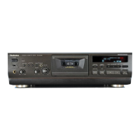
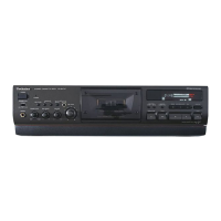
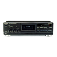
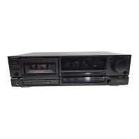
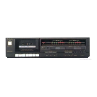
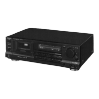
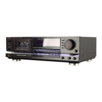
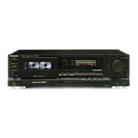
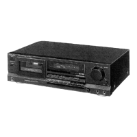
Overview of front panel controls, indicators, and remote operation functions.

Indicators Section

Indicator Descriptions

Detailed explanation of the meaning of each indicator light on the unit.

Disassembly Instructions

Cabinet and Main PCB Removal

Procedure for removing the unit's outer cabinet and main printed circuit board.

Front Panel and FL Drive PCB Removal

Steps for disassembling the front panel assembly and FL drive PCB.

Mechanism and Power Switch PCB Removal

Procedure for removing the mechanism unit and power switch/headphone PCB.

Internal Mechanism Part Removal

Detailed steps for removing internal mechanism parts like gears and levers.

Switch and Motor Component Removal

Instructions for removing leaf switches, eject motor, and drive sector lever.

Gear and Lever Installation

Procedures for installing drive gears and drive sector levers.

Measurement and Adjustment Methods

Measurement Conditions and Instruments

Essential conditions, instruments, and test tapes for unit measurements and adjustments.

Head Replacement and Alignment

Steps for replacing and adjusting the playback/record head for optimal performance.

Playback Adjustments

Procedures for adjusting playback gain and frequency response.

Bias and Erasure Adjustments

Methods for adjusting AC bias trap and erase current for optimal tape recording.

HX PRO Adjustment

Procedure for adjusting the HX PRO headroom extension circuit.

Frequency Response and Gain Calibration

Detailed steps for calibrating overall frequency response and gain.

REC CAL. Adjustment

Procedure for calibrating recording level and bias using the REC CAL function.

Terminal Function of ICs

Microcomputer Terminal Functions

Detailed pin functions for the microcomputer IC used in mechanical/FL drive operations.

Printed Circuit Boards

PCB Diagrams Overview

Diagrams illustrating the layout of various printed circuit boards in the unit.

Schematic Diagram

Circuit Schematic Details

Detailed schematic diagram of the unit's electronic circuits and their interconnections.

Troubleshooting of Direct Drive Motor

Direct Drive Motor System Overview

Explanation of the direct drive motor system and its servo control.

Direct Drive Motor Troubleshooting Guide

Common problems and solutions for the direct drive motor's operation.

Block Diagram

System Block Diagram

A high-level block diagram illustrating the unit's main functional blocks and signal flow.

Internal Connection of FL

FL Display Internal Connections

Details on anode and grid connections for the FL display.

Wiring Connection Diagram

PCB Interconnection Diagram

Diagram showing the wiring and connections between the unit's various PCBs.

Replacement Parts List

Cabinet, Chassis, and Accessories Parts

List of replacement parts for the unit's cabinet, chassis, and accessories.

Mechanical Exploded Views

Detailed exploded views of the unit's internal mechanical components.

Mechanism and Electronic Component Parts

List of replacement parts for the mechanism, transistors, and diodes.

Integrated Circuits and Transistors

List of replacement integrated circuits, transistors, and their specifications.

Variable Resistors and Sensors

List of replacement variable resistors, sensors, coils, and transformers.

Resistors, Capacitors, and Connectors

Detailed list of replacement resistors, capacitors, and connectors with their values.

Resistor Value Details

Continued list of resistors with specific part numbers and resistance values.

Capacitor Values List

List of replacement capacitors and their voltage and capacitance values.

Exploded Views

Cabinet Exploded Views

Illustrations showing the exploded view of the unit's cabinet parts.

Related product manuals