EasyManua.ls Logo

Technics RS-B555

Technics RS-B555
45 pages
To Next Page IconTo Next Page
Loading...
ORDER
NO.
AD8907231C5
MV
Cassette
Deck
Dolby
NR-Equipped
S-
Stereo
Cassette
Deck
R
Boo)
Color
*K
DU
(botsy
6-6
NA
AX
PAO)
[(W)..
Black
Type
Area
|
Country
|
;.
Code
|
(E,
E5)
|
Continental
Europe.
|
(K)
aoe
eaEGnE
|
(EB)
|
Great
Britain.
i
a
op
1
|
(EG)
|
F.R.
Germany
and
Italy
|
Ce
perce
acacia
ee
ce
*
HX
Pro
headroom
extension
originated
by
Bang
Olufsen
and
manufactured
under
license
from
Dolby
Laboratories
Licensing
Corporation.
“DOLBY”,
the
double-D
symbol,
and
“HX
PR
trademarks
of
Dolby
Laboratories
Licensing
Corporation.
MECHANISM
SERIES:
AR350
@
SPECIFICATIONS
SALE
EBAY!
nee
(3)
ac
@
CASSETTE
DECK
SECTION
Wow
and
flutter
Deck
system
Stereo
cassette
deck
Track
system
kK,
2-chann
Fast
forward
and
rewind
times
Heads
Approx.
90
Rec/play
lo
Input
sensitivity
and
impedance
Erasing
Mic
Motors
LINE
Capstan
;
Output
voltage
and
impedance
Reel
table
drive
;
LINE
Recording
system
AC
bias
HEADPHONES
Bias
frequency
80
kHz
Erasing
system
AC
erase
Tape
speed
4.8
cm/sec.
(1%
ips)
M@
GENERAL
Frequency
response
Power
consumption
a
NORMAL
20
Hz~18
kHz
Power
supply
20
Hz~16
kHz
(DIN)
For
U.S.A.
and
Canada
CrOz
20
Hz~18
kHz
For
Great
Britain
20
Hz~17
kHz
(DIN)
For
others
METAL
20
Hz~19
kHz
Dimensions
(W
x
H
x
D)
20
Hz~18
kHz
(DIN)
S/N
(signal
level=
re
ig
lev
2
tape)
Weight
Dolby
C
NR
on
74
dB
(CCIR)
Dolby
B
NR
on
66
dB
(CCIR)
Note:
Dolby
NR
off
56
dB
(A
weighted)
0
re
approximate.
Matsushita
Services
Company
Panasonic
Sales
Company,
Division
of
Matsushita
Electric
Division
of
Matsushita
Electric
Corporation
of
America
of
Puerto
Rico,
inc.
50
Meadowland
Parkway,
San
Gabriel
Industrial
Park
Secaucus,
New
Jersey
07094
65th
Infantry
Ave.
Km.9.5
@
ec
nics
Carolina,
P-R.
00630
Matsushita
Electric
Industrial
Question and Answer IconNeed help?

Do you have a question about the Technics RS-B555 and is the answer not in the manual?

Technics RS-B555 Specifications

General IconGeneral
BrandTechnics
ModelRS-B555
CategoryCassette Player
LanguageEnglish

Summary

Cassette Deck Specifications

General Specifications

Details on deck system, track system, heads, motors, bias, speed, and frequency response.

Performance Metrics

Wow and flutter, input sensitivity, output voltage, and power consumption details.

Safety Precautions and Accessories

Electrical Safety Precautions

Warnings and procedures to prevent electric shock during servicing.

Insulation Resistance Test Procedure

Steps to perform insulation resistance testing for electrical safety checks.

Included Accessories

List of items supplied with the unit, such as stereo connection cables.

Front Panel Controls and Functions

Control Descriptions

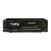
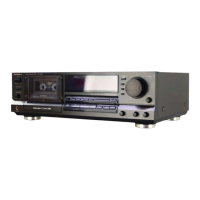
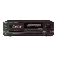
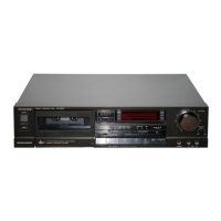
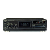
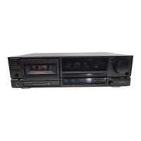
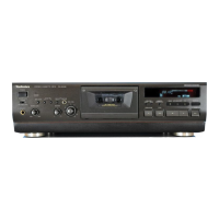
Explains each button, knob, and switch on the front panel.

Display Section Overview

Details of the display indicators, tape counter, and level meters.

Operation Section Details

Operation Buttons and Switches

Explains functions of buttons like Timer, Reset, Memory, APRS, Record, Pause.

Indicator Lights Explained

Details on indicators for Memory, Tape Select, APRS, MPX, and Dolby NR.

High Tone Quality Recording Guide

APRS Function for Recording

Explanation of the Advanced Precise Rec-Level System for optimal recording.

Setting the Recording Level

Step-by-step guide to adjust recording level using the APRS system.

System Overview and Connections

Direct Drive Motor System

Explanation of the capstan motor control system and its operation.

Rear Panel Connectivity

Description of input and output terminals on the rear panel.

Disassembly Instructions

Cabinet Removal Steps

Procedures for removing the main cabinet and rear panel.

Main PCB Removal

Steps to detach the main printed circuit board and its connectors.

Component Disassembly Procedures

Front Panel and Mechanism Unit Removal

Steps to remove the front panel, power switch, and mechanism unit.

Printed Circuit Board Removal

Specific PCB Removal Steps

Guides for removing FL drive, mic jack, rec level, and operation PCBs.

Cassette Holder and Eject Mechanism Removal

Eject Lever and Button Removal

Procedures for removing the cassette holder and eject lever/button assembly.

Measurement and Adjustment Methods

Measurement Conditions and Instruments

Required conditions, tools, and test tapes for adjustments.

Adjustment Points Diagram

Illustration of potentiometer locations on the main PCB.

Adjustment Procedures

Head Azimuth and Playback Gain Adjustment

Steps for aligning the playback head and setting playback gain.

Frequency Response and Bias Adjustment

Procedures for checking frequency response and setting AC bias.

Calibration Procedures

Overall Frequency Response Calibration

Adjusting frequency response for Normal, CrO2, and Metal tapes.

Overall Gain Adjustment

Setting the system's overall output gain level.

Integrated Circuit Pin Functions

IC901 Microcomputer Pin Details

Pinout and functions for the mechanism control microcomputer.

IC Pinouts and System Diagram

IC551 Microcomputer Pin Details

Pinout and functions for the FL meter control microcomputer.

System Block Diagram Overview

High-level overview of the unit's functional blocks.

FL Display Internal Connections

FL Display Wiring and Pinout

Detailed connection and grid layout for the FL display.

Schematic Diagrams

Main Circuit Schematic

Detailed circuit diagram for the core audio and control sections.

Schematic Diagram Details

Audio, Power, and Switch Circuit Schematics

Specific circuit sections for audio processing, power supply, and switches.

Schematic Diagram Details

Mechanism, FG, and Motor Control Schematics

Circuit diagrams for motor control and signal processing.

Troubleshooting and Component Guide

Direct Drive Motor Troubleshooting

Common issues and solutions for the Direct Drive motor.

IC, Transistor, and Diode Guide

Identification and terminal functions of key electronic components.

Printed Circuit Board Layouts

Main PCB Component Layout

Visual layout of components on the primary circuit board.

Printed Circuit Board Layouts

Other PCB Layouts

Layouts for FL Meter, Operation, Mic Jack, Power, and Reel Motor boards.

Printed Circuit Board Layouts

Mechanism and FG PCB Layouts

Layouts for the Mechanism and FG circuit boards.

Wiring Connection Diagram

Overall System Wiring Diagram

Comprehensive diagram showing interconnects between all unit parts.

Replacement Parts List

Integrated Circuits and Transistors

List of ICs and transistors with part numbers and remarks.

Replacement Parts List

Resistors, Coils, Connectors, and Switches

Details for variable resistors, coils, connectors, switches, and jacks.

Replacement Parts List

Cabinet, Mechanism, and PCB Parts

Parts list for cabinet, mechanism assemblies, and printed circuit boards.

Exploded Views - Cabinet

Cabinet Assembly Breakdown

Visual representation of cabinet parts and their assembly.

Exploded Views - Mechanical

Mechanism Component Breakdown

Visual breakdown of internal mechanical parts and their locations.

Mechanism Parts List

Mechanism Component Identification

Detailed list of mechanism parts with part numbers.

Resistors and Capacitors List

Resistor Specifications

Comprehensive list of resistors, values, and remarks.

Resistors and Capacitors List

Capacitor Specifications

Comprehensive list of capacitors, values, and remarks.

Resistors and Capacitors List

Additional Capacitor Data and Packing

Further capacitor details and packing instructions.

Technical Information

Mechanism Composition and Detection Switches

Overview of the mechanism's structure and detection mechanisms.

Technical Information

Mechanism Mode Setting and Operation

Explanation of how mechanism modes are set and initiated.

Technical Information

Reel Table and Brake Operation Details

Explanation of reel table rotation and brake engagement.

Technical Information

Mechanism Control Circuit Operation

How the microcomputer controls the mechanism.

Technical Information

Mechanism Operation Timing Chart

Visual representation of timing for key mechanism operations.

Technical Information

Linear Magne-field Class AA Recording Amplifier

Description of the advanced recording amplifier technology.

Technical Information

APRS System Detailed Explanation

In-depth explanation of the APRS recording level system.

Service Manual Updates and Changes

Replacement Parts List Changes

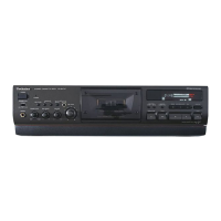
Noted differences in replacement parts for RS-B565 compared to RS-B555.

Service Manual Updates and Changes

Additional Part Number Changes

Further modifications to replacement part numbers for various components.

Service Manual Updates and Changes

Packing Instructions

Guidelines for properly packing the unit.

Service Manual Updates and Changes

PCB and Exploded View Updates

Revisions to circuit board layouts and exploded views.

Related product manuals