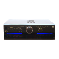
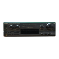
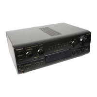
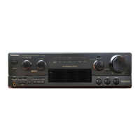
Do you have a question about the Technics SA-AX6 and is the answer not in the manual?
Technical details including amplifier and tuner sections.
Details power output, distortion, damping factor, and frequency response.
Details frequency range, sensitivity, selectivity, and distortion.
Emphasizes that the manual is for experienced technicians only and warns of severe injury or death.
Explains the function and troubleshooting steps for the protection circuitry.
Detailed steps on how to safely replace the fuse in the AC mains plug.
Shows how to connect audio sources like CD players and turntables.
Illustrates video connections for TVs, VCRs, and camcorders.
Details connections for DVD players, including discrete 6-channel and 2-channel outputs.
Explains how to connect devices using S-VIDEO terminals and provides troubleshooting tips.
Shows how to connect speakers to the 'A' terminals for front, center, and surround.
Details connecting a second pair of speakers to the 'B' terminals.
Provides a visual guide on how to correctly connect speaker cables, including polarity.
Guides on selecting speaker configurations (A, B, BI-WIRE) for optimal sound.
Explains how to choose the desired audio/video source using the INPUT SELECTOR.
Covers adjusting the main volume and subwoofer level for balanced audio.
Instructions on how to turn the front panel blue light on or off.
Guides on adjusting bass, treble, and sound balance for desired audio output.
Explains how to mute the sound level using the remote control.
Instructions for connecting and listening through headphones, including speaker disabling.
Explains the SUBWOOFER ADAPTIVE CONTROL for enhancing sound at low volumes.
Guide to selecting the appropriate low-pass filter frequency for the subwoofer.
Details adjusting the high and low frequency balance for BI-WIRE speakers.
Explains how to use the TV/VCR2 input select button with front VCR2 terminals.
Steps for recording audio from various sources onto a tape deck.
Instructions for recording audio onto VCR 1.
Details the steps for setting the sleep and wake timers and checking remaining times.
Provides step-by-step procedures for checking the operation of individual printed circuit boards.
Outlines procedures for replacing key internal components.
Detailed steps for replacing the Power IC and Regulator Transistor.
Details the pin assignments and functions for the main microprocessor IC.
Defines signal lines, switch functions, and component notations used in the schematics.
Highlights important safety precautions when working with static-sensitive components and during repairs.
Schematics for volume, loudness, motor drive, and related control functions.
Diagrams for subwoofer level control, LED drivers, and headphone jack connections.
Part details for structural and chassis components.
List of integrated circuits with part numbers and functions.
List of transistors with part numbers and remarks.
List of diodes with part numbers and remarks.
List of variable resistors (potentiometers) with part numbers and values.
List of switches with part numbers and remarks.
List of connectors with part numbers and remarks.
List of coils, transformers, and filters with part numbers.
List of oscillators and ceramic filters with part numbers.
Part details for the display tube.
List of fuses with part numbers.
List of fuse holders with part numbers.
List of combined components with part numbers.
List of jacks, HP connectors, and earth terminals with part numbers.
List of wires, wire units, and earth wire units with part numbers.
Details resistors by reference number, part number, and value.
Details capacitors by reference number, part number, and value.
Details items like packing cases, polyform, and bags used for packaging.
Lists accessories such as remote controls, O/I books, AC cords, and antennas.
| Tuning Range | FM, MW |
|---|---|
| Damping Factor | 30 |
| Channel Separation | 55dB (line) |
| Video Connections | Composite |
| Power Output | 100 W per channel into 8Ω (stereo) |
| Impedance | 8Ω to 16Ω |
| Inputs | Phono, CD, Tape, VCR |
| Input Sensitivity | 2.5mV (MM), 150mV (line) |
| Signal to Noise Ratio | Line: 100 dB |
| Speaker Load Impedance | 4Ω to 16Ω |
| Dimensions | 430 x 159 x 329 mm |