Do you have a question about the Technics SA-CH950 and is the answer not in the manual?
Details power output, harmonic distortion, impedance, and frequency response for the main amplifier.
Provides frequency range, sensitivity, and signal-to-noise ratio for the FM tuner.
Lists frequency range and signal-to-noise ratio for the AM tuner.
Guidance on preparing for repairs and understanding the unit's protection circuitry.
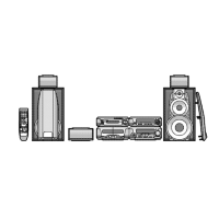
Lists all accessories provided with the main unit for setup and use.
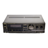
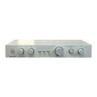
Details the function and layout of all controls and displays on the unit's front panel.
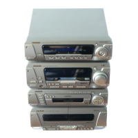
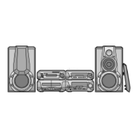
Diagrams showing how to stack components horizontally or vertically for optimal system setup.
Guides for connecting flat cables, antennas, speaker cords, and surround speaker cords.
Instructions for connecting external units like televisions, DAT decks, video decks, and analog players.
How to connect the center speaker and surround speakers for optimal audio playback.
Instructions for integrating a video disc player into the system for audio and video playback.
Detailed instructions for setting the current time and day using the unit's controls.
Procedures for safely removing the outer cabinet and front panel assembly.
Guides for detaching the FL P.C.B. and rear grill assembly.
Procedures for removing various PCBs, power components, and the fan assembly.
Guide for replacing unit feet and other removable parts.
Visual representation of the tuner circuit's electronic components and connections.
Detailed schematic of the front panel FL (Fluorescent) display circuit and its control.
Schematic illustrating the connections and components for the headphones jack.
Schematics detailing the main circuit, power transformer, and AC input terminal connections.
Visual representation of the attenuator circuit responsible for signal level adjustment.
Schematic detailing the input and output terminal connections for external devices.
Layouts for the tuner, FL display, and input/output terminal printed circuit boards.
Diagram for the attenuator PCB and a guide to common components.
Shows the internal wiring connections between various PCBs and external interfaces.
Explains the purpose of each pin on the IC601 chip for system control.
Visual representation of the main functional blocks and their interconnections within the system.
Diagram showing signal paths, volume control, and power amplifier connections.
Catalog of replacement parts for ICs, coils, and filters, including part numbers and descriptions.
List of replacement parts for switches, transistors, diodes, connectors, and fuses.
Comprehensive list of resistors with their part numbers, values, and remarks.
Detailed list of capacitors, including part numbers, values, and applicable areas.
Continuation of the capacitor list, detailing part numbers, values, and remarks for various components.
Lists and identifies part numbers for cabinet components and packing materials.
Identifies part numbers for accessories such as remote control, antennas, and cords.
Illustrated guide showing the placement and assembly of all cabinet parts.
Visual guide illustrating how each component of the system is packaged for protection.
Printed circuit board layout for the E-Board, showing component locations.
Printed circuit board layout for the M-Board, detailing component placement.
Printed circuit board layout for the Y-Board, indicating component locations.
Printed circuit board layout for the B-Board, showing component placement and connections.
Detailed schematic of the E-Board circuit, showing component interconnections and signal paths.
Detailed schematic of the A-Board circuit, illustrating component placement and signal flow.