EasyManua.ls Logo

Technics SA-CH750

Technics SA-CH750
26 pages
To Next Page IconTo Next Page
Loading...
Service
Manual
Tuner
Amplifier
Tuner
Amplifier
SA-CH750
Colour
eFor
(E),
(EB),
(EG)
areas
SL-CH750
SH-CH750
Remote
Control
Transmitter
+
|
(Kyi
cent
acces
Black
Type
Areas
Suffix
for
Model
No.
Colour
SB-CH750A/CH755
RS-CH750
SA-CH750
SB-CH750A/CH755
eFor
(GC),
(GN)
areas
Great
Britain
Remote
Control
SL-CH750
SH-CH750
Germany
and
Italy
(k)
Transmitter
Asia,
Latin
America,
Middle
Near
East
and
Africa
Oceania
System:
SC-CH750
SB-CH750
RS-CH750
SA-CH750
SB-CH750
Because
of
unique
interconnecting
cables,
hen
a
component
requires
service,
send
r
bring
in
the
entire
system.
SPECIFICATIONS
(DIN
45
500)
ie
ee
Fe
ows,
@
Main
Amp.
Section
Power
output
DIN
1
kHz
THD
1%
both
channel
driven
For
(GC),
(GN)
areas
SFP,mode1kHzTHD1%
_
[toevn
nail
AN
TUNER
SECTION
MAIN
|
Eee
NEE
ncy
range
SURROUND
2x5
W
(8Q)
MW
Total
harmonic
distortion
For
(E),
(EB),
(EG),
(GN)
areas
522-1611
kHz
(9
kHz
steps)
Rated
power
at
1
kHz
1%
(6)
530-1620
kHz
(10
kHz
steps)
Half
power
at
1
kHz
0.09%
(6Q)
For
(GC)
area
531-1602
kHz
(9
kHz
steps)
Load
impedance
530-1600
kHz
(10
kHz
steps)
MAIN
6-80
LW
SURROUND
8
For
(E),
(EB),
(EG),
(GN),
areas
9
144~—288
kHz
Q
kHz
steps)
S/N
(rated
power)
84
dB
For
(GC)
area
153-279
kHz
@
kHz
steps)
Frequency
response
40
Hz—30
kHz
(—3
dB)
Sensitivity
(S/N
20
dB)
MW
500
uVv/m
m@
FM
Tuner
Section
LW
50
uV
Frequency
range
87.50
MHz—108.00
MHz
(0.05
MHz
steps)
Sensitivity
1.8
pV
(IHF,
usable)
@
Timer
Section
S/N
26
dB
1.5
yV
(75Q)
Clock
Quartz-lock
type
S/N
Function
24-hour
programmable;
Play
trmer
(1
time)
MONO
70
dB
(75
GB,
IHF)
Rec
trmer
(1
time)
Stereo
separation
at
1
kHz
35
dB
Sleep
(120
min.
1
min.
intervals)
Antenna
terminal(s)
75Q
(unbalanced)
Setting
1
minute—23
hours
59
minutes
(1
min.
intervals)
Sound
processor
|
Tuner
amplifier
|
Compact
disc
player
|
Cassette
deck
Speakers
*SB-CH750A
............
(E),
(EB),
(EG)
areas
SC-CH750
SH-CH75'
SA-CH750
SL-CH750
RS-CH750
*SB-CH795
cesccds
2
esate
aa
Baytthes
Switzerland
only
SB-CH750
................
(GC),
(GN)
areas
*Magie
in
PAES
Technics
Question and Answer IconNeed help?

Do you have a question about the Technics SA-CH750 and is the answer not in the manual?

Technics SA-CH750 Specifications

General IconGeneral
BrandTechnics
ModelSA-CH750
CategoryAmplifier
LanguageEnglish

Summary

SPECIFICATIONS

Main Amplifier Section

Details amplifier power output, load impedance, and total harmonic distortion.

FM Tuner Section

Covers FM frequency range, sensitivity, and signal-to-noise ratio.

AMLW Tuner Section

Outlines AM and LW frequency ranges and sensitivity.

Timer Functions

Describes clock and timer functions like programmable timers and sleep.

GENERAL INFORMATION

Power Supply and Specifications

Details power consumption, voltage, and current specifications.

Physical Dimensions and Weight

Lists the physical dimensions and weight of the unit.

Important Notes and Disclaimers

Contains important notices regarding specifications and measurements.

REPAIR AND MAINTENANCE

Before Repair Procedures

Instructions for safely discharging capacitors and performing initial power-up checks.

Protection Circuitry Operation

Explains causes of protection activation and the procedure to reset it.

ACCESSORIES

Included System Accessories

Lists all accessories included in the package, such as cords and batteries.

LOCATION OF CONTROLS

Front Panel Controls

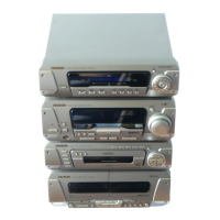
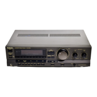
Identifies and explains the function of buttons and knobs on the front panel.

Front Panel Display Indicators

Details the meaning of various indicators shown on the unit's display.

COMPONENT STACKING

Horizontal and Vertical Arrangements

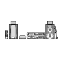
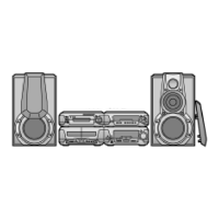
Illustrates component stacking options for different system layouts.

CONNECTING THE FLAT CABLE AND FM ANTENNA

Initial Cable Setup

Guides on connecting the flat cable and the FM indoor antenna.

CONNECTING THE LWMW ANTENNA AND SPEAKERS

Speaker and Antenna Cable Connections

Instructions for connecting LW/MW antenna, speaker cables, and surround speakers.

CONNECTING THE AC POWER SUPPLY

Final Power Connection

Details the procedure for connecting the AC power cord to the unit.

SETTING THE TIME OF DAY

Time Setting Procedure

Step-by-step guide to set the current time on the unit.

DISASSEMBLY INSTRUCTIONS

Cabinet and Front Panel Removal

Details procedures for removing the outer cabinet and front panel assembly.

PCB and Rear Grill Removal

Outlines steps for removing the FL P.C.B., rear grill, and associated components.

SCHEMATIC DIAGRAM - MAIN, POWER TRANSFORMER (A)(B) AND AC IN TERMINAL CIRCUIT

Main Circuit and Power Supply Schematics

Provides detailed schematics for the main, power transformer, and AC input terminal circuits.

SCHEMATIC DIAGRAM - INPUTOUTPUT TERMINAL CIRCUIT

InputOutput Terminal Circuit Schematic

Details the schematic for the input/output terminal circuit.

SCHEMATIC DIAGRAM - TUNER CIRCUIT

Tuner Circuit Schematic Diagram

Presents the schematic diagram for the tuner circuit.

PRINTED CIRCUIT BOARD DIAGRAM

Main and Tuner PCB Layouts

Shows the printed circuit board layouts for the main and tuner sections.

BLOCK DIAGRAM

System Block Diagram Overview

Illustrates the overall system architecture and signal flow.

FUNCTION OF IC TERMINALS

IC Terminal Function Descriptions

Lists and explains the function of terminals for key integrated circuits.

REPLACEMENT PARTS LIST

Component Part Numbers and Descriptions

Provides a comprehensive list of replaceable parts with their part numbers.

Related product manuals