Do you have a question about the Technics SA-EH750 and is the answer not in the manual?
Details power output, distortion, impedance, and sensitivity for the amplifier.
Covers frequency range and sensitivity for the AM tuner.
Describes clock, timer, and sleep functions.
Provides power supply, consumption, dimensions, and weight.
Explains the protection mechanism and reset procedure for speaker connections.
Lists included accessories like power cords, antennas, and remote.
Warns about unsuitable plugs and severe electrical shock danger.
Details wiring color codes for AC mains lead connection.
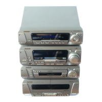
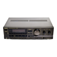
Describes the buttons and indicators on the main tuner amplifier unit.
Explains the buttons and operations of the remote control unit.
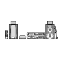
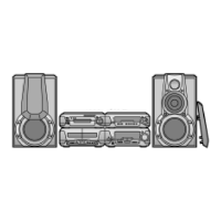
Guides on positioning the CD changer, tuner amplifier, speakers, etc., for optimal setup.
Provides recommendations for center, surround, and wall-mounting speakers.
Illustrates how to connect speaker wires to the tuner amplifier and speakers.
Shows how to connect the AC power cord and antenna terminals.
Instructions for inserting batteries into the remote control.
Guidelines for aiming the remote and avoiding obstacles.
Explains connections for 5.1 channel and standard DVD players.
Describes how to connect a VCR for audio playback.
Details how to connect outdoor antennas for improved reception.
Step-by-step guide for setting the 24-hour clock on the unit.
Explains how to activate ECO mode for reduced standby power consumption.
Detailed instructions for inserting CDs into the changer trays.
Important precautions to avoid damaging CDs and the unit.
How to play CDs in sequence, including stopping and skipping tracks.
How to select and play specific tracks or discs directly.
How to set the unit to repeat playing all tracks or favorite tracks.
How to play tracks in a random, non-sequential order.
How to program up to 24 tracks for playback in a custom sequence.
How to activate or deactivate the Super Woofer feature.
How to choose between HEAVY, CLEAR, AI EQ, MANUAL, and FLAT sound settings.
How to reset the sound quality setting to FLAT.
How to adjust bass, midrange, and treble levels using the manual equalizer.
How to reset the manual equalizer settings to FLAT.
How to adjust surround level and sound quality using the AI EQ.
How to reset the AI EQ settings to FLAT.
Using 5.1 channel Dolby Digital sources with compatible DVD players.
Enjoying Dolby Surround sources with the unit's built-in circuitry.
Adds surround effects to movie/music or stereo effects to monaural sources.
Makes surround sound seem to come from behind.
Makes center speaker sound appear to come from the TV.
Creates the sensation of multiple surround speakers.
Maintains sound position despite listener movement.
How to set individual speaker levels for optimal 5.1 channel playback.
How to select and play Dolby Pro Logic sources.
How to set individual speaker levels using the test signal.
How to select MOVIE or MUSIC modes for 5-channel surround effects.
How to manually adjust the output level of surround speakers.
Makes center speaker sound appear to come from the TV.
Makes surround sound seem to come from behind.
Creates the sensation of multiple surround speakers.
Adds stereo-like effects to monaural sound sources.
Adjusts listening position for better effect, especially with virtual rear surround.
Explains the different spectrum display types: Normal, Peak-hold, Aurora.
How to select and play audio from external devices.
Steps for recording audio from external sources onto a cassette tape.
How to record audio from the unit onto an external device.
Procedures for checking the tuner and power supply circuit boards.
Procedures for checking the operation circuit board.
Procedures for removing and checking the main circuit board.
Step-by-step guide for replacing regulator transistors.
Step-by-step guide for replacing the power IC.
How to display error codes indicating malfunctions (U70, F61).
Explains error codes, problems, and correction procedures like checking flat cables.
Lists the page number for the tuner circuit schematic.
Lists the page numbers for the operation circuit schematic.
Lists the page numbers for the main circuit schematic.
Lists the page number for the power supply circuit schematic.
Lists the page number for the speaker terminal circuit schematic.
Lists page numbers for power transformer circuits (A & B).
Diagram showing the component layout for the tuner printed circuit board.
Diagram showing the component layout for the power supply printed circuit board.
Diagram showing the component layout for the operation printed circuit board.
Diagram showing the component layout for the main printed circuit board.
Diagram for the speaker terminal PCB.
Diagram for the power transformer (A) PCB.
Diagram for the power transformer (B) PCB.
Shows wiring between Main and Tuner PCBs.
Illustrates connections for power supply and transformers.
Shows wiring for speakers to the Main PCB and Terminal PCB.
Pin functions for the system control IC.
Pin functions for other ICs like LC72, IC101, IC102, IC151.
Illustrates the tuner and IF signal processing blocks.
Shows the PLL synthesizer, decoder, and data processing blocks.
Shows the system control IC and its connections to FL display.
Illustrates audio processing ICs like M62456FPE1 and LC72721NMTLM.
Shows the power amplifier IC (RSN311W64) and its connections.
Illustrates power transformer and regulator circuit blocks.
Lists replacement parts for capacitors (C101-C701).
Lists replacement parts for resistors (R102-R998).
Lists replacement parts for diodes, ICs, connectors, and other components.
Lists replacement parts for diodes (D101-D758, D901-D974).
Lists replacement parts for ICs, transistors, connectors, and other parts.
Lists replacement parts for transistors (Q701-Q906).
Lists replacement parts for resistors (R102-R998).
Lists replacement parts for transformers, oscillators, and other miscellaneous components.
Lists replacement parts for resistors (R910-R998).
Lists replacement parts for transformers, oscillators, switches, and other miscellaneous components.
Exploded view and part numbers for the main unit's chassis and front panel.
Lists part numbers for speaker grilles, badges, screws, and other cabinet parts.
Diagrams showing how the main unit and accessories are packaged for shipping.
| Power Output | 100 W |
|---|---|
| Input Sensitivity | 250 mV |
| Type | Stereo Receiver |
| Output Power / Channel | 100 W |
| Tuner Bands | FM/AM |
| Preset Station Qty | 30 |
| Display Type | Fluorescent |
| Frequency Response (Audio) | 10 Hz - 20 kHz |
| Input Impedance | 47 kΩ |
| Tuning Range | 87.5 - 108 MHz (FM), 531 - 1602 kHz (AM) |