Do you have a question about the Technics SE-CH404 and is the answer not in the manual?
Details power, distortion, impedance, S/N, and frequency response.
Covers power consumption, dimensions, and weight.
Procedure for safely discharging capacitors before power-on.
Verifying consumed current at different supply voltages.
Identifies symptoms and outlines steps to reset protection.
Instructions for setting the voltage selector for the GC area.
Note on AM stereo broadcast reception in AM mono.
Safety advice regarding the moulded plug and fuse.
Instructions on how to safely replace the fuse.
Explains wire colors (Brown/Live, Blue/Neutral) for connection.
Lists AC power cords, remote transmitter, and batteries.
Details flat cables, antennas, mounting hardware, and adapters.
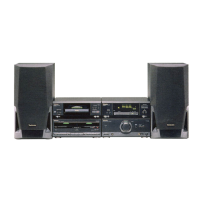
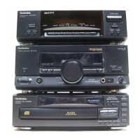
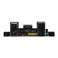
Illustrates horizontal and vertical arrangements of system components.
Provides a visual example of component placement for stereo sound.
Instructions for connecting flat cables and the FM indoor antenna.
Steps for connecting loop antenna and speaker cables.
Information on outdoor antennas and AC power cord.
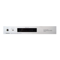
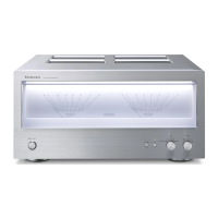
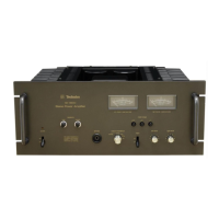
Identifies and describes controls on the front panel, including power, volume, and jacks.
Procedure for turning the amplifier on/off via AC cord and TP701 shorting.
Steps to remove the main cabinet, front panel, and rear grill.
Procedures for removing power transformer PCB and fan assembly.
Steps to detach the main PCB and volume control PCB.
Details on removing/replacing power ICs/transistors with silicone compound.
Method for removing old feet and attaching new ones.
Visual representation of the system's functional blocks and signal flow.
Detailed electrical circuit schematics for the unit.
Layouts of the printed circuit boards (PCBs) with component references.
Illustrates how various components and PCBs are interconnected.
Illustrates how individual components and the complete system are packaged.