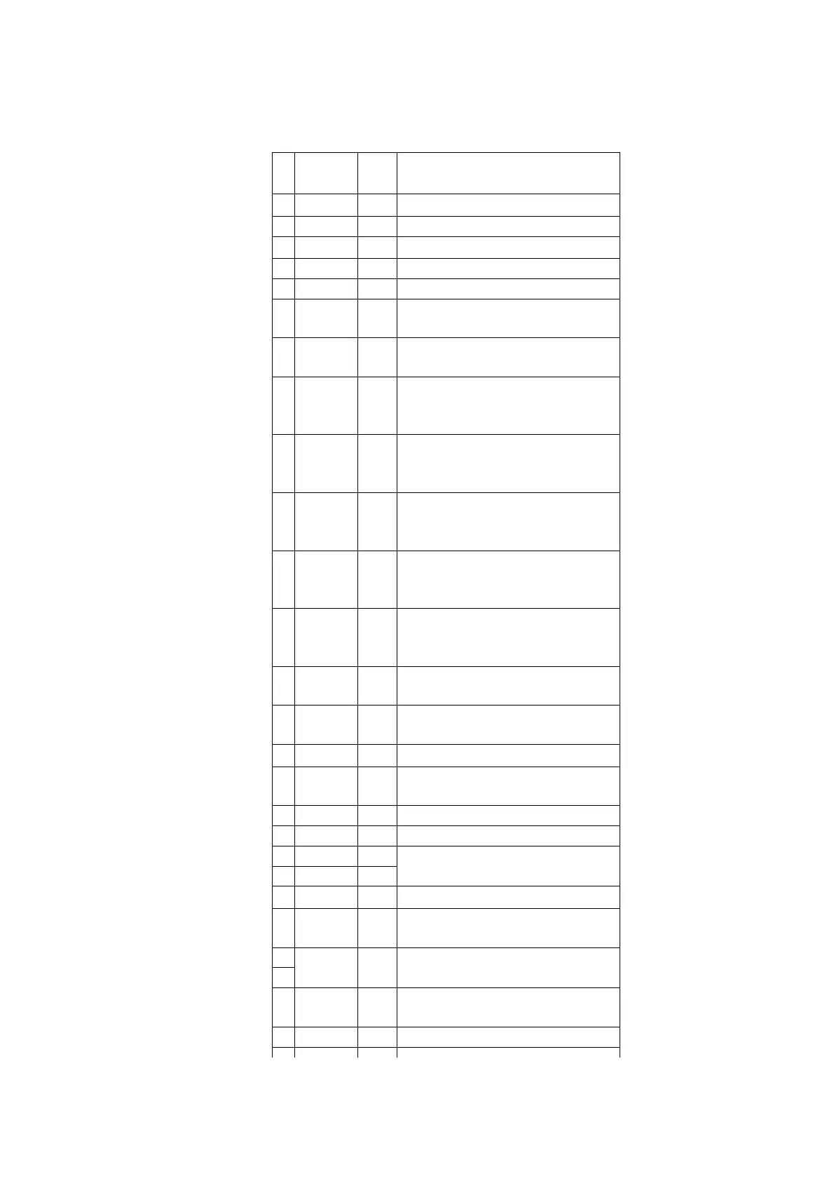
Pin
No.
Terminal
Name
I/O Function
1
V
cc
I Power supply terminal
2 VREF I Reference voltage input
3
AV
SS
- GND terminal
4 SYNC I Power failure detect signal input
5 SUBQ I Sub-code Q data signal input
6 SQCK O Sub-code Q resistor clock
signal output
7 BLKCK I Sub code block clock signal
input
8 B REQ I Serial communication request
signal input from FL display/
System control IC
9 B CS O Serial communication CS signal
output for FL display/System
control IC
10 B CLK O Serial communication clock
signal output for FL display/
System control IC
11 DATA O O Serial communication data
signal output for FL display/
System control IC
12 DATA I I Serial communication data
signal input from FL display/
System control IC
13 CW O Loading motor control signal
(OPEN) output
14 CCW O Loading motor control signal
(CLOSE) output
15
CNV
SS
- GND terminal
16 SERVO
RST
O Reset signal output
17 NC - Not used, open
18 RESET I Reset signal input
19 X IN I Oscillator connected terminal (F
=6 MHz)
20 X OUT O
21
V
SS
- GND terminal
22 LED
ORG
O LED (orange) control signal
output
23 NC - Not used, open
24
25 LED
GRN
O LED (green) control signal
output
26 TEST O TEST mode signal output