EasyManua.ls Logo

Technics SL-EH60

Technics SL-EH60
39 pages
To Next Page IconTo Next Page
Loading...
ORDER
NO.
AD9703028C8
Service
Manual
Compact
Disc
Player
CD
Changer
SL-EH60
System:
SC-EH60
Colour
(KK)
ieseaendeeteietsie
Black
SL-EH60
SH-EH6O
pune
*
SB-PC60
*'
SB-EH60
SB-EH60
Area
(E)(EP)
...
Europe,
Russia,
Asia,
Latin
America,
Middle
East,
Africa
and
Oceania.
*
SB-PS60
COMPACT
DIGITAL
AUDIO
Remote
Control
Transmitter
M
A
S
H
#3
multi-
stage
noise
shiping
Because
of
unique
interconnecting
cables,
when
a
component
requires
service,
send
or
bring
in
the
entire
system.
RAE0150Z
MECHANISM
SERIES
Specifications
Audio
Section
General
DA
converter
:
1
bit
DAC
MASH
Dimensions
:
287(W)/89(H\/336(D)
mm
.
ight
:
2.4k
Pickup
Section
werent
ss
Wavelength
:
coon
Notes
:
Specifications
are
subject
to
change
without
notice.
Weight
and
dimensions
are
approximate.
System/SC-EH60:
Sound
processor:
SH-EH60,
Tuner/Amplifier:
SA-EH60,
Compact
disc
changer:
SL-EH60,
Cassette
deck:
RS-EH6
0,
Front
speakers:
*'
SB-EH60,
Center
speaker:
*?
SB-PC60,
Surround
speakers:
*?
SB-PS60
Notes:
*1...For
Europe
and
Russia
:
Made
in
PAES,
For
others
:
Made
in
MESA
*2...Made
in
MESA
*3...MASH
is
a
trademark
of
NTT
Z\WARNING
This
service
information
is
designed
for
experienced
repair
technicians
only
and
is
not
designed
for
use
by
the
general
public.|t
does
not
contain
warnings
or
cautions
to
advise
non-technical
individuals
of
potential
dangers
in
attempting
to
service
a
product.
Products
powered
by
electricity
should
be
serviced
or
repaired
only
by
experienced
professional
technicians.
Any
attempt
to
service
or
repair
the
product
or
products
dealt
with
in
this
service
information
by
anyone
else
could
result
in
serious
injury
or
death.
Technics
©
1997
Matsushita
Electric
Industial
Co.,
Ltd.
All
rights
reserved.
Unauthorized
copying
and
distribution
is
a
violation
of
law.
;
E
3
:
3
3
F
One
Meee
eT
Question and Answer IconNeed help?

Do you have a question about the Technics SL-EH60 and is the answer not in the manual?

Technics SL-EH60 Specifications

General IconGeneral
TypeCD Player
Frequency Response2Hz-20kHz
Total Harmonic Distortion0.003%
Channels2 (stereo)
Dynamic Range96dB
Output Voltage2V
Digital Output1 (optical)

Summary

Product Specifications

Audio and Pickup Specifications

Details on audio sections, pickup wavelength, and general system specs.

General System Information

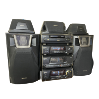
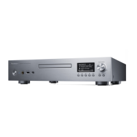
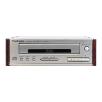
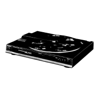
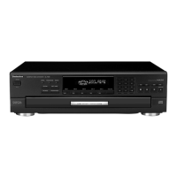
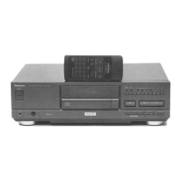
Component overview, color, and regional variations for the SC-EH60 system.

Safety Precautions

Laser Diode Safety

Procedures to avoid hazardous radiation exposure from the laser diode.

Electrostatic Discharge Handling

Precautions for preventing damage to the optical pickup from static electricity.

Unit Controls and Operation

Location of Controls

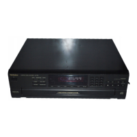
Identifies buttons and indicators on the SL-EH60 unit.

Transport Mode Setup

Instructions for setting the unit to transport mode for shipping or storage.

Compact Disc Playback

Loading and Checking CDs

Step-by-step guide on how to load, unload, and check CDs in the player.

Damage Prevention

Important points to observe to prevent damage during CD playback.

Disc Playback Modes

Sequential and One-Touch Play

Explains how to perform sequential play and one-touch play operations.

Stopping and Pausing Playback

Instructions for stopping, temporarily stopping, and resuming disc playback.

Service Procedures

CD Changer DisassemblyReassembly

Detailed steps for taking apart and putting back together the CD changer unit.

P.C.B. Checking Procedures

Guides for checking the main, operation, and servo printed circuit boards.

Component Replacement Procedures

Steps for replacing major components like the traverse deck and servo P.C.B.

Troubleshooting and Adjustment

Error Code Display and Servo Adjustment

Using error codes and servo adjustment for fault diagnosis.

Troubleshooting Guide

Flowchart for diagnosing playback issues and component failures.

Diagrams and Schematics

Schematic Diagrams

Circuit diagrams for various sections of the unit.

Printed Circuit Board Diagrams

Visual representation of component placement on PCBs.

Wiring Connection Diagram

Illustrates how different PCBs and components are interconnected.

IC Terminal Functions

System Control IC (IC401)

Details pinout and function for the system control IC.

Servo Amplifier ICs (IC701, IC702)

Details pinout and function for servo amplifier and signal processor ICs.

Motor Driver IC (IC703)

Details pinout and function for the traverse/spindle motor driver IC.

Replacement Parts Lists

Electrical Parts List

List of electrical components with part numbers and descriptions.

Resistors and Capacitors

Detailed list of resistors and capacitors with their values and locations.

Cabinet and Loading Unit Parts

List of cabinet, loading unit, and mechanical parts with part numbers.

Location Illustrations

Cabinet Parts Location

Diagrams showing the location of external cabinet components.

Loading Unit Parts Location

Diagrams illustrating the placement of parts within the loading unit.

Related product manuals