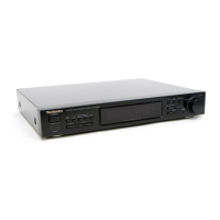
This document is a service manual for the Technics FM Stereo Tuner ST-9030, covering models (X), (XG), (XGH), (XGF), (XSD), (XSW), and (XE). It provides detailed technical specifications, a description of its internal circuits, alignment instructions, and a block diagram.
The ST-9030 is an FM stereo tuner designed to receive FM radio broadcasts. Its primary function is to convert FM radio signals into an audio output, allowing users to listen to radio stations with high fidelity. The tuner incorporates advanced circuitry for signal processing, including IF (Intermediate Frequency) wide-narrow automatic change-over, muting, and stereo separation optimization, to ensure clear and stable reception even in challenging signal environments.
Function Description
The tuner operates by receiving FM signals through its antenna terminals. These signals are then processed through several stages:
- RF Amplifier and Mixer: The incoming FM signal is amplified and mixed with a local oscillator signal to produce an Intermediate Frequency (IF) signal.
- IF Amplifier: The IF signal is further amplified and filtered. The ST-9030 features both "wide" and "narrow" IF bandwidths. The "wide" setting offers higher fidelity but is more susceptible to interference from adjacent stations, while the "narrow" setting provides better selectivity in crowded broadcast environments. The tuner includes an automatic change-over circuit that intelligently switches between these bandwidths based on signal conditions and the presence of interference.
- Ratio Detector: This stage demodulates the FM signal, converting it into an audio signal.
- FM MPX PLL Demodulator (IC601 AN363): For stereo broadcasts, the demodulated signal, which contains multiplexed stereo information, is fed into a Phase-Locked Loop (PLL) demodulator. This circuit separates the left and right audio channels, along with pilot tones and subcarriers.
- Muting Circuit: The ST-9030 incorporates a sophisticated muting circuit to suppress inter-station noise and weak, noisy signals. This circuit utilizes three main components: a muting band switch, an S/N (Signal-to-Noise) level switch, and an IF band range switch. This design allows for adjustable muting levels and bandwidths, providing effective noise reduction without compromising desired signals.
- Output Stages: The processed audio signals are then sent to various output terminals, including fixed (REC OUT) and variable (OUTPUT) stereo outputs, as well as a 4-channel MPX output.
Important Technical Specifications (IHF)
- Frequency Range: 88 ~ 108 MHz
- Antenna Terminals: 75Ω (unbalanced)
- Sensitivity:
- 12.8 dBf (75Ω) 1.2 µV (IHF '58)
- 50 dB Quieting Sensitivity:
- MONO: 18.1 dBf (75Ω) 2.2 µV (IHF '58)
- STEREO: 38.1 dBf (75Ω) 22 µV (IHF '58)
- Total Harmonic Distortion (Wide/Narrow):
- MONO (1kHz): 0.08% / 0.15%
- STEREO (1kHz): 0.08% / 0.3%
- S/N (Signal-to-Noise) Ratio:
- Frequency Response:
- OUTPUT: 20 Hz ~ 18 kHz, +0.1 dB, -0.5 dB
- REC OUT: 20 Hz ~ 15 kHz, +0.2 dB, -0.8 dB
- Alternate Channel Selectivity (Wide/Narrow): 25 dB / 90 dB (400 kHz)
- Capture Ratio (Wide/Narrow): 0.8 dB / 2.0 dB
- Image Rejection (at 98 MHz): 135 dB
- IF Rejection (at 98 MHz): 135 dB
- Spurious Response Rejection (at 98 MHz): 135 dB
- AM Suppression (Wide): 58 dB
- Stereo Separation (Wide):
- 1 kHz: 50 dB
- 10 kHz: 40 dB
- (Narrow):
- 1 kHz: 40 dB
- 10 kHz: 30 dB
- Leak Carrier (19 kHz):
- OUTPUT: -65 dB
- REC OUT: -70 dB (19 kHz, 38 kHz)
- Output Voltage:
- Fixed (REC OUT): 0.7 V
- Variable (OUTPUT): 0 ~ 1.5 V
- Power Supply: 110/120/220/240 V (50/60 Hz)
- Power Consumption: 27 W
- Dimensions (W x H x D): 450 x 92 x 370 mm (17¾" x 3⅝" x 14½")
- Weight: 7.4 kg (16.3 lb.)
Usage Features
- IF Select Switch: Allows users to manually select "auto" or "wide" IF bandwidths. The "auto" mode automatically switches between wide and narrow bandwidths to optimize reception.
- Servo Tuning/Muting Switch: This switch controls the servo tuning and muting functions, with "auto/muting on" and "off" positions. The servo tuning system helps maintain precise tuning, while muting suppresses noise between stations.
- MPX Hi-Blend Switch: Provides an "auto" or "off" setting for the hi-blend function. This feature can reduce noise in weak stereo signals by blending high frequencies, though it may slightly reduce stereo separation.
- Output Level Control: A variable control for adjusting the output volume.
- Signal Strength Meter and Tuning Meter: Visual indicators on the front panel to assist with accurate tuning and signal assessment.
- 4CH MPX Output: Provides a dedicated output for connecting to external 4-channel decoders or processors.
- Voltage Selector: The unit supports multiple AC line voltages (110/120/220/240V), making it adaptable to different regions.
Maintenance Features
The service manual provides comprehensive instructions for alignment and troubleshooting, crucial for maintaining the tuner's performance.
- Alignment Instructions: Detailed steps are provided for aligning various sections of the tuner, including IF and RF alignment, output level alignment, mono distortion alignment, wide/narrow IF output level alignment, and muting alignment. These procedures involve using specialized equipment such as VTVMs, oscilloscopes, FM signal generators, frequency counters, and distortion meters.
- Dial Cord Installation Guide: Specific instructions are given for threading a fresh dial cord, including cord length, variable capacitor positioning, and tensioning.
- Schematic Diagrams and Block Diagrams: The manual includes detailed schematic diagrams for the entire unit and block diagrams for integrated circuits, which are essential for technicians to understand the circuit operation and diagnose faults.
- Component Identification: The diagrams clearly label components, aiding in part replacement and repair.
- Safety Notice: A shaded area on the schematic diagram highlights critical components important for safety, emphasizing the use of manufacturer-specified parts for these areas during servicing.
- Voltage Values: Indicated voltage values on the schematic diagrams serve as standard references for troubleshooting, measured with a DC electronic circuit tester (high impedance) with the chassis as standard.
The ST-9030 is designed for enthusiasts who appreciate high-quality FM reception and offers a robust set of features for optimizing audio performance and signal clarity. Its detailed service manual ensures that the device can be effectively maintained and repaired, extending its lifespan and preserving its performance.