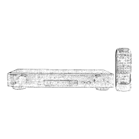
SU-C800UM2
|
m@
Contents
Page
Page
Front Panel
Controls
.........cccsccssscerssecesereseeersencsseeee
nicdauidananctdea’.
2
Wiring
Connection
Diagram
......ussesssscssssessssesssscesssscseseestssstescstsenee
13
Operation
Check
and
Type
lilustration
of
IC's;
Transistors
and
Diodes
................:sseseeesese
13
Main
Component
Replacement
Procedures
...........:csscssecereeees
3,4
ERMC
DUST
55s
sesscincsttance
Gicivceves
as
Sevcrienennvicandonsannaiavenstrapsdsbncalnats
14
To
Supply
Power
Source
.0......
ccc
cesessesseeessseesereesereesneeeseecentesestassatens
5
Replacement
Parts
List
(Electrical)
.........ccsscsvsstscssscesserrsnersenees
15,16
Terminal
Function
of
IC'S
00...
cecesccnssecseseeseeeessesecseeeecevseeneneeacanenteenes
6
Replacement
Parts
List
(Cabinet)
............:.ccsscssssesssseeseessessesersaesneeee
16
Schematic
Diagram
«oo...
escsescsssessencsncssssessevesseceesessesseceeaesessesees
6-10
Replacement
Parts
List
(Resistors
and
Capacitors)...
17
Printed
Circuit
Board
Diagram
......
RE
ee
ee
aat
a
aOR
eee
11,
12
Cabinet
Parts
Location
.0.........ccccscccccssceccnsccueeccessecsesesusnccesenssanensauanees
18
NOTE:
Refer
to
the
service
manual
for
Model
No.
SE-A900SM2
(ORDER
No.
AD9707099C2)
or
SE-A800SM2
(ORDER
No.
AD9707098C2)
for
information
on
“Accessories”,
“Connections”
and
“Packaging”.
@
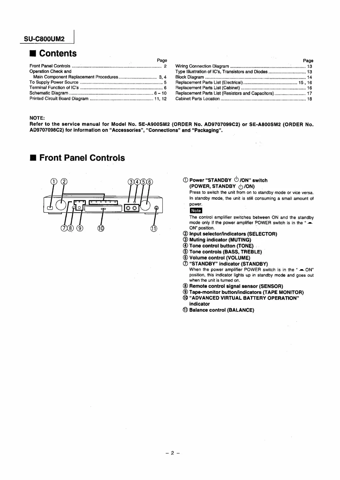
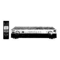
Front
Panel
Controls
@
Power
“STANDBY
(!
/ON”
switch
(POWER,
STANDBY
(ty
ON)
Press
to
switch
the
unit
from
on
to
standby
mode
or
vice
versa.
In
standby
mode,
the
unit
is
still
consuming
a
small
amount
of
power,
The
control
amplifier
switches
between
ON
and
the
standby
mode
only
if
the
power
amplifier
POWER
switch
is
in
the
“=
ON’
position.
Ay
@
Input
selector/indicators
(SELECTOR)
@®
Muting
indicator
(MUTING)
—
@
Tone
contro!
button
(TONE)
-
©
Tone
controis
(BASS,
TREBLE)
©
Volume
control
(VOLUME)
@
“STANDBY”
indicator
(STANDBY)
When
the
power
ampiifier
POWER
switch
is in
the
“
=m
ON”
position,
this
indicator
lights
up
in
standby
mode
and
goes
out
when
the
unit
is
turned
on.
Remote
control
signal
sensor
(SENSOR)
@
Tape-monitor
button/indicators
(TAPE
MONITOR)
(9
“ADVANCED
VIRTUAL
BATTERY
OPERATION”
indicator
@
Balance
control
(BALANCE)