Do you have a question about the Technics SU-V10X and is the answer not in the manual?
Detailed power output and distortion specifications for the main amplifier stage.
Input sensitivity, impedance, and S/N ratio for the preamplifier stage.
Procedure for testing insulation resistance to prevent electrical shock hazards to users.
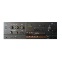
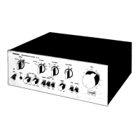
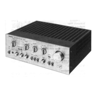
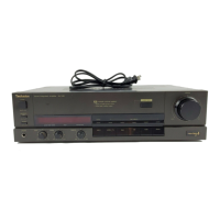
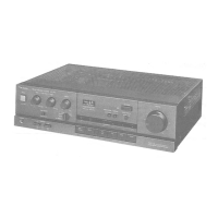
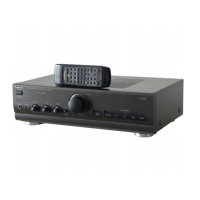
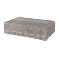
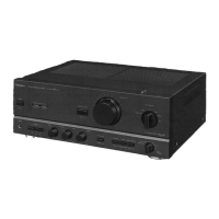
Identification and function of front panel controls, switches, and indicators.
Description of various input and output terminals for audio and video signals.
Step-by-step guide for basic unit operation, including power, speakers, and source selection.
Provides helpful tips for noise reduction and optimal listening experiences.
Instructions on how to record audio and video sources, including tape-to-tape copying.
Explains the function of protection circuitry and troubleshooting steps when it activates.
Initial steps and procedure for removing the unit's outer cabinet.
Detailed steps for removing the front panel assembly.
Instructions for removing the sub panel and specific circuit boards like AUX2/VIDEO.
Steps to remove the indicator panel and selector buttons/PCBs.
Procedure for removing the bottom access panel of the unit.
Explains the function of each pin for the MN1421STA IC controller.
Details the function of each pin for the µPD7506C043 analog function control IC.
A reference guide for identifying terminals of various transistors, diodes, and ICs.
Step-by-step guide on how to safely and correctly replace integrated circuits.
Overall schematic showing how major components and PCBs are interconnected.
Visual layouts identifying the components and connections on various printed circuit boards.
Procedure for adjusting the idle current (bias) for optimal amplifier performance.
Steps to verify the functionality of the overload detection circuit.
Illustrates the overall signal path and how different functional blocks interact.
Detailed schematic for power supply regulation, rectification, and speaker output circuits.
Schematic details for tone control, impedance selector, and voltage amplifier sections.
Schematic diagrams covering the main power supply and fuse protection circuits.
Diagrams showing circuits that differ based on geographical area ([EGA] and [XA]).
List of components with part numbers, descriptions, and quantities required for replacement.
Visual diagram showing the exploded view of the unit and the location of major parts.