EasyManua.ls Logo

Technische Alternative ESR 21 Series - User Manual

Technische Alternative ESR 21 Series
40 pages
Print Icon
To Next Page IconTo Next Page
Loading...
ESR 21
Version / Versione / Versión 7.9
Simple solar control unit
Régulateur solaire simple
Regolatore semplice a energia solare
Regulación solar sencilla

Questions and Answers

  • A
    Andrew JamesAug 3, 2025
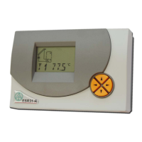
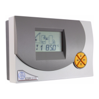
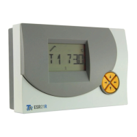
    Why is my Technische Alternative ESR 21 displaying incorrect temperatures?
    • D
      Darrell CummingsAug 3, 2025
      If your Technische Alternative Control Unit shows values like -999 (sensor short-circuit) or 999 (interruption), it doesn't automatically indicate a hardware issue. Ensure the correct sensor types (KTY or PT1000) are selected in the menu under SENSOR, as the default setting is PT (1000). To check the sensor, replace the potentially faulty sensor with a known working one on the terminal strip to verify the display.
  • A
    agarciaAug 12, 2025
    What to do if my Technische Alternative ESR 21 Control Unit system is not in operation?
    • S
      Stanley FisherAug 13, 2025
      If your Technische Alternative Control Unit isn't working despite having power, check the 3.15A quick-blowing fuse that protects the control system and the output. Replace the fuse if necessary.
  • K
    Kristina DeanAug 23, 2025
    How to troubleshoot a malfunctioning Technische Alternative ESR 21 Control Unit with realistic temperature values?
    • J
      joshua47Aug 23, 2025
      If your Technische Alternative Control Unit is malfunctioning but displaying plausible temperatures, consider these checks: * Verify the program number. * Examine the switch-on and switch-off thresholds and the set differential temperatures to see if they've been reached. * Check if settings in the submenus have been altered. * Test the output in manual mode to ensure it can be switched on and off. If it responds correctly during an endurance run, the unit is likely in order. * Confirm that all sensors are connected to the correct terminals. You can test a sensor by heating it with a lighter and observing the display.

Summary

Hydraulic Diagrams

Program 1

Details about program 1 for solar thermal systems with an additional storage limit.

Sensor Installation

Sensor Lines

Information on sensor line cross-sections, extension limits, and connection methods.

Installing the Device

Instructions for physically mounting the control unit and connecting internal components.

Electrical Connection

Data Link (DL)

Details on the bi-directional data link for PC communication and compatible hardware.

External Sensors

Instructions for reading external sensors via the DL connector.

Safety Requirements

Operation

The Main Level

The Parameter Menu Par

Changing a Value (Parameter)

The Menu Men

Status Display Stat

Tips on Troubleshooting

EU Declaration of Conformity

Technische Alternative ESR 21 Series Specifications

General IconGeneral
Housing MaterialPlastic
Connection TypeScrew terminals
Number of Relays4
Number of Analog Inputs4
InputsDigital, Analog
OutputsRelay
DisplayLCD
Humiditynon-condensing
Relay Contact Rating230 V AC
Analog Input Type0-10 V, 0-20 mA

Related product manuals