C
Craig CannonJul 25, 2025
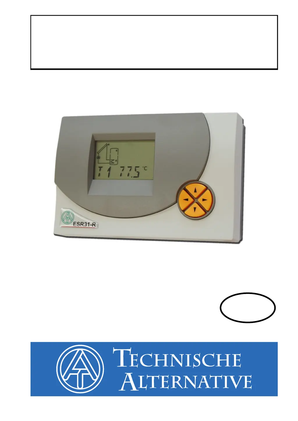
What to do if my Technische Alternative ESR31-R Control Unit malfunctions but shows realistic temperature values?
- MmharrisJul 26, 2025
If your Technische Alternative Control Unit shows a malfunction but displays 'realistic' temperature values, consider the following checks: * Verify the program number. * Examine the switch-on and switch-off thresholds, along with the differential temperatures that were set. * Determine if the thermostat and differential thresholds have been reached. * Check for any settings changes made in the submenus (MEN). * Test if the output can be toggled on and off in manual mode. * Ensure all sensors are connected to the correct terminals. To test the sensors, heat them up using a lighter and monitor the display for changes.