EasyManua.ls Logo

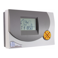
Technische Alternative ESR 31 Series

Technische Alternative ESR 31 Series
56 pages
To Next Page IconTo Next Page
Loading...
ESR 31
Version 2.0 EN
Simple solar control unit
Operation
Installation instructions
en

Questions and Answers:

Technische Alternative ESR 31 Series Specifications

General IconGeneral
BrandTechnische Alternative
ModelESR 31 Series
CategoryControl Unit
LanguageEnglish

Summary

Safety requirements

Maintenance

Information on proper care and upkeep for the device.

Generally applicable rules for the correct use of this control unit

Hydraulic diagrams

Program 0 - 2 -Solar thermal system

Diagram for solar thermal systems with initial factory settings.

Program 4 - 7 - Loading pump control

Diagrams for controlling the loading pump in solar systems.

Program 8, 9 - Air flap control for an earth collector

Diagrams for controlling an earth collector air flap.

Program 12 - Burner requirement using holding circuit

Diagram for burner control using a holding circuit.

Operation

The main level

Overview of the primary display and navigation interface.

Changing a value (parameter)

Procedure for modifying parameter values within the system.

The parameter menu PAR

Code number CODE

Accessing and managing system parameters via a code.

Software version VR VD

Device software version details.

Program number PR

Selection of operational program for the system.

Set values (min, max, diff)

Configuration of system thresholds and differentials.

Automatic manual mode

O AUTO

Automatic operation mode settings.

C AUTO

Control output manual mode settings.

The menu MEN

Brief description

Overview of menu functions and settings.

SENSOR

Configuration of sensor inputs and types.

SYS PF

System protection and safety functions.

STARTF

Start-up assistance for solar thermal systems.

ART

Setting the pump after-run time.

PSC

Pump speed control settings (ESR31-D).

COP

Control output configuration (0-10V/PWM).

F CHCK

Activation and use of the function check.

HQC

Heat quantity counting and configuration.

EXT DL

External sensor data interface.

Sensor settings

Sensor type

Creating a mean (average) AV

System protection functions SYS PF

Collector excess temperature limiter

Function to block the pump at high collector temperatures.

Frost protection

Function to prevent damage from freezing temperatures.

Collector excess temperature CET

Collector anti-freeze FROST

Start function STARTF (ideal for tube collectors)

After-running time ART

Pump speed control PSC (only ESR31-D)

Absolute value control

Differential control

Event control

Stability problems

Pump standstill

Control commands

Control output COP 0-10 V PWM

Function check F CHCK

Heat quantity counter HQC

Tips on accuracy

Step by step setting of the heat quantity counter

External sensors EXT DL

Status display Status

Collector excess temperature is active

Excess temperature detected, CETOFF active.

Function check is active

Monitoring for sensor defects and circulation errors.

Installation instructions

Sensor installation

Proper arrangement and installation of system sensors.

Sensor lines

Guidelines for extending and connecting sensor cables.

Installing the device

Electrical connection

Instructions for safe and correct electrical hook-up.

Tips on troubleshooting

Table of settings

Technical data

EC- DECLARATION OF CONFORMITY

Related product manuals