46
Installation instructions
Sensor installation
The sensors must be properly arranged and installed for the system to function correctly.
Collector sensor (red or grey cable with connection box): Either insert the sensor in a
pipe directly soldered or riveted to the absorber and extending out of the collector casing
or screw the sensor onto a T piece on the end of the supply line’s collecting tube using
an immersion sleeve. No water may be allowed to enter the immersion sleeve (danger of
freezing).
Storage sensor: The sensor should be used with an immersion sleeve just above the
outlet for the exchanger’s return line if heat exchangers with ribbed tubes are used and
with a T piece on the outlet of the exchanger’s feed line if integrated non-ribbed tubes are
used. It should not be installed below the respective register or heat exchanger in any
case.
Boiler sensor (boiler supply line): This sensor is either screwed into the boiler using an
immersion sleeve or at a short distance from the boiler on the supply line.
Pool sensor (swimming pool): Install directly at the outlet from the pool on the suction
line as an attached sensor (see attached sensor). Installation using an immersion sleeve
is not recommended due to the possibility of condensation within the sleeve.
Clip-on sensor: Optimally secured using roll springs, pipe clamps or hose band clips to
the line. Make sure the material used is proper (corrosion, temperature resistance, etc.).
Then, the sensor has to be well insulated so that the pipe temperature is measured ex-
actly and the ambient temperature does not influence the measurement.
Warm water sensor: to produce warm water using an external heat exchanger a rapid
reaction to changes in water quantity is absolutely critical. For this purpose the ultra-fast
warm water sensor (special accessory) must be installed directly to the heat-exchanger
output using T-shaped connector and installation kit.
Sensor lines
All of the sensor lines with a cross-section of 0.5mm2 can be extended up to 50m. With this
length of line and a Pt1000 temperature sensor, the measurement error is approx. +1K.
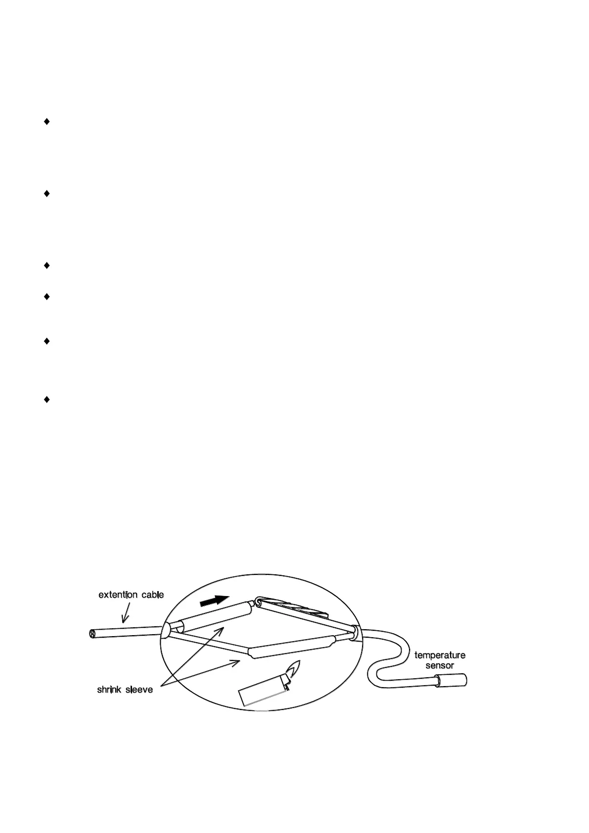
Longer lines or a lower measurement error require an appropriately larger cross-section. The
sensor and the probe can be connected by putting the heat-shrinkable sleeve truncated to 4
cm over a wire and twisting the bare ends. If one of the wire ends is tinned then the connec-
tion must be made through soldering. Then the heat-shrinkable sleeve is put over the bare,
twisted ends and carefully heated (such as with a lighter) until it has wrapped the connection
tightly.
In order to prevent measurement fluctuations, the sensor cables must not be subject to
negative external influences to ensure fault-free signal transmission. When using non-
screened cables, sensor cables and 230V network cables must be laid in separate cable
channels and at a minimum distance of 5 cm.
 Loading...