35
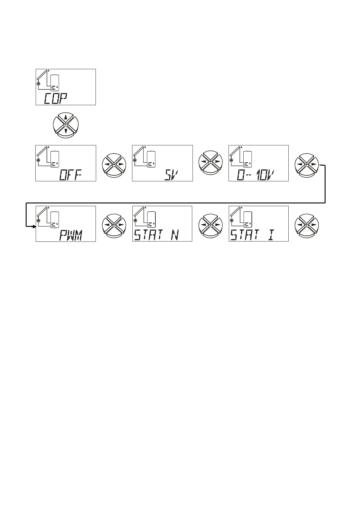
Control output COP 0-10 V / PWM
Different functions of the control output
Control output
deactivated
5V power supply
for vortex sensors
Error message
(upon error 0 to
10 V switchover)
Error message
(upon error in-
verse switchover
from 10 to 0V)
OFF Control output deactivated; output = 0V
5V Power supply for vortex sensors without DL connection
(VF2, VTS) output = 5V
0–10V PID – controller; output= 0-10V in 0.1V increments
PWM PID – controller; output = duty cycle 0-100% in 1% increments
STAT N / STAT I If function control is activated and an error message is displayed in the
status display Stat (sensor open circuit IR, -short circuit SC or circulation error
CIRC.ER) the output with the setting STAT N is switched over from 0 to 10 V (for
STAT I: inversely from10V to 0V). Upon collector excess temperature switch-off
CETOFF, the control output does not switchover. Subsequently, the auxiliary relay
HIREL-STAG can be connected to the control output, which forwards the error
message to a signalling device (e.g. warning lamp or audible alarm).
 Loading...