Do you have a question about the Technogym EXCITE+ VARIO and is the answer not in the manual?
Technogym recommends steps for planning effective repair procedures.
General guidelines and rules to follow for all repair operations.
Explanation of the alphanumeric characters used in machine product codes.
Details the 14 alphanumeric characters that constitute the serial number.
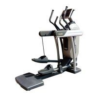
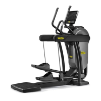
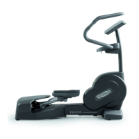
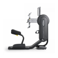
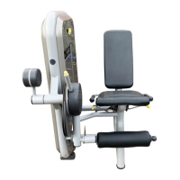
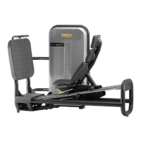
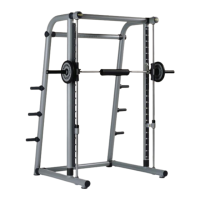
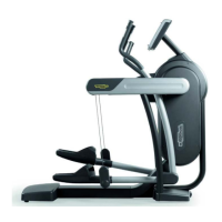
Overview of key features for various EXCITE models.
Provides overall dimensions and weight specifications for the machine.
Specifies the required operating and storage temperature and humidity.
Lists the standards and directives the machine complies with.
Illustrates the electrical connections for different machine models.
Details specific cable types, signals, and pin assignments.
Details the specific connection cables used for Unity models.
System block diagram illustrating components for LED, Visio, and Visioweb models.
System block diagram illustrating components for the Unity model.
Details the ARM Board and C-Safe Board functionalities.
Describes the CPU Board for the 700VISIO model.
Explains the function of the LCD inverter for powering display lamps.
Details the tuner board for receiving audio/video signals.
Enables local network connectivity for VISIO devices.
Enables Wi-Fi connectivity for VISIO devices.
Port for connecting USB devices for updates and data transfer.
Details the Main Board, CPU Module, Wi-Fi, and Controller TS of Unity.
Describes various components of the Unity device like NFC, TV Tuner, TGS Reader.
Manages signals from telemetric transmitters and hand sensors.
Functions related to power supply and RS-485 communication.
Explanation of the eddy current brake mechanism and operation.
Description of the non-adjustable magnetic brake mechanism.
Explains the mechanics and control of the brake systems.
Details the RS-485 signal, excitation current, and sensor pulses.
Instructions for connecting the machine to Cardio Theater.
Procedure for connecting to a PC for machine programming.
Details the monitor plug for C-Safe port testing.
Lists optional accessories like TGS Reader and iPod Docking Station.
Essential specifications and requirements for proper machine installation.
Instructions for safely moving the equipment manually or with a trolley.
Step-by-step guide for correctly installing the machine.
Steps for initial power-on and operational checks.
Guide to accessing troubleshooting menus for LED models.
Guide to accessing troubleshooting menus for Visio models.
Flowchart for diagnosing and resolving display illumination issues.
Troubleshooting steps for touch screen calibration or non-functionality.
Troubleshooting steps for problems with audio and radio functionality.
Troubleshooting steps for issues with the TV display.
Troubleshooting steps for resolving iPod connection problems.
Resolving error messages related to communication loss.
Explanation of brake board error codes and their solutions.
Steps to diagnose and resolve issues when no resistance is generated.
Steps to diagnose and resolve issues with incorrect resistance levels.
Steps to diagnose and resolve issues with the speed signal.
Troubleshooting steps for errors related to the TGS reader.
Steps to diagnose and resolve issues with the heart rate signal.
Troubleshooting steps for incorrect telemetry heart rate signals.
Step-by-step guide for removing the complete display unit.
Instructions for removing the front frame protective casings.
Procedure for safely removing the brake board.
Procedure for removing the brake belt.
Steps for disassembling the pulley, primary assembly, and shaft.
Disassembly of secondary shaft, brake, flywheel, and belt tensioner.
Disassembly of the arms movement, magnetic brake, and toothed belt.
Instructions for removing upper frame protection and handlebars.
Procedure for disassembling platform lever and primary connection belts.
Steps for removing the platform lever assembly.
Instructions for disassembling the total body lever.
Correct tension values for the brake and toothed belts.
Procedure for adjusting the short belt tension and alignment.
Procedure for adjusting the long belt tension and alignment.
Instructions for applying grease to the belts.
Procedure for adjusting magnet position for the speed sensor.
Instructions for leveling the machine using its feet.
User menu settings and parameters for 500 LED models.
User menu settings and parameters for 700 LED models.
Accessing service menus for LED models.
Accessing and modifying parameters for the lower assembly.
Accessing machine usage data stored in the low kit.
Accessing and managing the machine's error history log.
Resets brake board parameters to their default values.
User menu settings and parameters for Visio and Visioweb models.
Service menu access and configuration for Visio and Visioweb models.
Configuration options specific to the Unity model.
Procedure for updating the software on Visio and Visioweb models.
Procedure for updating the software on Unity models.
Performing essential safety tests on the grounding ring.
Checks for correct assembly of transmission, levers, and guards.
Checks to perform after installation or technical intervention.
Identifies critical components that require traceability.
Guidelines for routine and major maintenance operations.
Lists access passwords for various configuration menus.
Refers to the TG SERVICE TOOLS BOX LIST for disassembly and maintenance.
| Brand | Technogym |
|---|---|
| Model | EXCITE+ VARIO |
| Category | Fitness Equipment |
| Language | English |