Do you have a question about the Technogym SYNCHRO Excite + and is the answer not in the manual?
Manual is for authorized Technogym Service technicians, detailing repairs and maintenance procedures.
Steps for planning repair procedures: evaluate, diagnose, plan, access components.
Rules for repairs: mark parts, use original parts, consult newsletters, use specified tools.
Details the 16-alphanumeric characters forming the machine code and their key values.
Defines the 14 alphanumeric characters of the serial number and their key values.
Presents available colour options for the frame and upholstery.
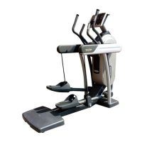
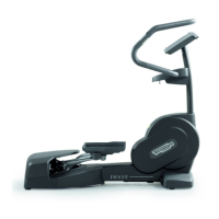
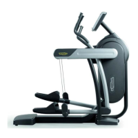
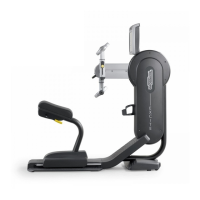
Compares characteristics of different models (700VISIO, 700, 700SP, 500, 500SP).
Details mechanical specifications like width, length, height, and weight.
Provides overall dimensions of the machine in mm and inches.
Illustrates packing dimensions for European and overseas shipping.
Specifies operating and storage temperature and humidity ranges.
Lists standards and directives the machine conforms to for EMI, Safety, and Directives.
Provides detailed wiring diagrams for various machine models and configurations.
Wiring diagram for the powered model 500, showing component connections.
Wiring diagram for the self-powered model 500SP, detailing component connections.
Wiring diagram for the powered model 700, illustrating component interconnections.
Wiring diagram for the self-powered model 700SP, showing component interconnections.
Wiring diagram for the powered model 700VISIO, detailing CPU board connections.
Details specifications and pinouts for various machine cables.
Details CBQ-13 (C-Safe Board) and CBQ32 (TGS) cable pinouts and colours.
Details CU132 (TGS) and CU128 (Power) cable specifications and pinouts.
Details ELT-01 (Generator), ELT-02 (Brake power), and ELT-04 (High/Low Kit) cables.
Illustrates the machine's block diagram, showing component interconnections for different versions.
Details the various LED display boards, their functions, and indicator LEDs.
Details the ARM board functions, features, and indicator LEDs for 500/500SP models.
Details the ARM board functions, features, and indicator LEDs for 700/700SP models.
Describes the C-Safe board, its communication port, and PC interfacing capabilities.
Explains the Dual TGS Reader's function for interacting with the Wellness System.
Details the various VISIO display boards, their functions, and components.
Details the 700VISIO CPU board, its components, functions, and indicator LEDs.
Explains the function of the CPU board's battery for maintaining the internal clock.
Describes the LCD inverter's function in powering LCD display lamps.
Explains the tuner board's role in receiving and managing audio/video signals.
Details the integrated LAN network board for connecting the VISIO device to a local network.
Describes the wireless network board enabling Wi-Fi connectivity for the VISIO device.
Covers Audio/Video connectors, Headphone Jack, C-Safe, and Service USB port.
Details optional accessories: iPod docking station, Client USB port, and Dual TGS reader.
Details the cardio receiver board and its components.
Explains the HS receiver's function for hand sensors and signal processing.
Details the HR receiver's function for chest belts and its negative logic communication.
Describes the two models of brake boards, their sections, and indicator LEDs.
Explains the eddy current brake's operating principle and its components.
Details the speed sensor's function for detecting brake disk rotation for powered models.
Describes the power entry module for powered models, including its components and current limits.
Explains the alternator's function in generating voltage for self-powered models.
Details the 12V battery for self-powered models, its function, and recharging methods.
Describes the socket for the external power supply used to recharge the battery.
Explains the mechanics, controls, and signals involved in the brake system.
Explains the mechanical aspects of brake control, including shafts and speed sensor signal.
Illustrates the control block diagram for the brake system and its operation.
Details the control signals used: RS-485, Excitation current, and Pulses.
Explains connecting the machine to the Cardio Theater via RJ45 on the C-Safe board.
Describes connecting to a PC for programming using the RJ45 connector on the C-Safe board.
Details the monitor plug for C-Safe port testing and LED indication.
Explains the differences between VISIO and VISIOWEB and the upgrade procedure.
Explains the differences between VISIO and VISIOWEB and the upgrade procedure.
Covers upgrade kits for converting LED Display to VISIO Display, based on TV standard.
Lists accessory codes for Dual TGS Reader, iPod Docking Station, and USB port.
Outlines requirements for correct machine installation: surface, environment, and power.
Provides instructions on how to safely move the equipment, recommending two people.
Refers to a separate manual for detailed information on antenna signal requirements.
Step-by-step procedure for correctly installing the machine, including powered and VISIO models.
Guides through the initial power-on procedure and checks for correct machine operation.
Procedure to access troubleshooting menus for LED models, including password entry.
Steps to access configuration for 500 models via password and menu options.
Steps to access configuration for 700 models via password and menu options.
Describes automatic tests for machine operation checks, including I2C Devices Test.
Checks communication between I2C devices and the display board, with possible outcomes.
Checks LED functionality and buzzer by varying frequency; requires visual inspection.
Tests communications on C-Safe, Low Kit, and TGS serial ports, with success/error outcomes.
Covers manual tests for machine operation, including Keyboard Test.
Tests all keyboard keys for proper functioning by checking for audible feedback.
Procedure to activate the troubleshooting menu for VISIO models via screen touch sequence and password.
Troubleshooting guide for display illumination failures on various models.
Flowchart for troubleshooting display illumination issues on LED models.
Flowchart for troubleshooting display illumination issues on SP models.
Flowchart for troubleshooting display illumination issues on VISIO models.
Troubleshooting for Touch Screen, Audio, TV Picture, and Radio problems on VISIO models.
Flowchart for troubleshooting iPod connectivity and functionality issues on VISIO models.
Troubleshooting for communication loss between High Lit and Low Kit, causing the error message.
Flowchart for diagnosing and resolving issues when the machine produces no resistance.
Flowchart for diagnosing and resolving issues with incorrect resistance levels.
Flowchart for diagnosing and resolving issues with an incorrect speed signal.
Flowchart for troubleshooting TGS reader errors, checking voltage and communication.
Troubleshooting guide for heart rate signal issues.
Troubleshooting for Hand Sensor issues, including human body continuity and correct use.
Troubleshooting for Chest Belt HR signal issues, including receiver mounting and SW version.
Troubleshooting guide for telemetry heart rate signal issues.
Flowchart for troubleshooting telemetry HR signal from chest belt, checking SW and grounding.
Troubleshooting for Hand Sensor HR signal issues, checking SW version and cable wear.
Procedure to disassemble the display unit for various models.
Procedure to disassemble the display unit for 500 and 500SP models.
Procedure to disassemble the display unit for 700 and 700SP models.
Procedure to disassemble the display unit for the 700VISIO model.
Steps for disassembling boards and components from the display unit.
Steps for disassembling boards and components from the LED display unit.
Detailed steps to remove the ARM board from the LED display unit.
Detailed steps to remove the C-Safe board from the LED display unit.
Lists components to be removed from the VISIO display, including CPU board and others.
Procedure for disassembling the wireless board from the VISIO display.
Procedure for disassembling the Tuner DVB-T board from the VISIO display.
Procedure for disassembling ATSC and ISDB-T tuner boards from the VISIO display.
Procedure for disassembling the LCD inverter board from the VISIO display.
Procedure for disassembling the CPU board from the VISIO display.
Procedure for disassembling the LCD and touch screen assembly from the VISIO display.
Procedure for disassembling the headphone jack from the VISIO display.
Procedure for disassembling the Dual TGS reader and USB port assembly from the VISIO display.
Procedure for disassembling the iPod docking station from the VISIO display.
Procedure for disassembling the front plugs and cover from the VISIO display.
Procedures for disassembling the keyboard and touch screen for LED and VISIO models.
Procedures for disassembling the keyboard and touch screen for LED and VISIO models.
Refers to specific procedure for Touch Screen disassembly on VISIO models.
Step-by-step guide to disassemble the cardio receiver unit.
Procedure for disassembling the fixed handgrips, including levers and tray brackets.
Procedure for disassembling hand sensors on powered versions (700, 700SP, 700VISIO).
Steps for disassembling various guards, including rear, brake box cover, and front guards.
Procedure for disassembling the rear guard.
Procedure for disassembling the brake box cover guard.
Procedure for disassembling the front guards.
Detailed steps for disassembling the levers, including plastic plugs, connectors, and screws.
Procedure for disassembling the brake box, including screws, connectors, and brake board replacement.
Procedure for disassembling the hand sensor board, including clips and glue removal.
Steps to disassemble the primary shaft and pulley, including screws, bearings, and extractor use.
Procedure for disassembling the platform lever, including screws, bearings, and plugs.
Procedure for disassembling the brake winding, including fastons, screws, and replacement.
Procedure for disassembling the flywheel and belt tensioner.
Procedure for disassembling the flywheel and belt tensioner on powered models.
Procedure for disassembling the flywheel group on self-powered models.
Procedure for disassembling the speed sensor on powered models (500, 700, 700VISIO).
Procedure for disassembling the battery on powered models (500SP and 700SP).
Procedure for disassembling footboards, power entry module, and wheels.
Procedure for adjusting the belt tension, including specific measurements and cautions.
Procedure for positioning the speed sensor correctly, including measurements and tightening.
Procedure for positioning the brake winding, including centering the copper disk and testing.
Troubleshooting and adjustment for the machine not being flat, by adjusting the feet.
Procedure to access and configure 500LED models via user menu and password.
Setting the machine's display language from available options.
Selecting between European and Imperial units for measurement display.
Setting the maximum duration for each exercise session, ranging from 1 to 9999 minutes.
Setting the maximum pause time for exercises, ranging from 10 to 999 seconds.
Setting the cooldown time for exercises, ranging from 5 to 180 seconds.
Setting the default age for a generic user, ranging from 10 to 99 years.
Setting the default weight for a generic user, ranging from 10 to 99 kilograms.
Setting the default duration for exercise sessions, ranging from 1 to 999 minutes.
Setting the default calories for exercise sessions, ranging from 10 to 999.
Setting the default distance for exercise sessions, ranging from 1 to 999.
Enabling or disabling the use of the TGS reader.
Disabling the keyboard to allow usage only with the TGS.
Enabling or disabling target heart rate modification during constant HR exercise.
Configuring custom messages to be displayed in standby state.
Resetting user menu parameters to their default values.
Formatting a TGS key for Plug&Play mode operation.
Displays the machine's serial number.
Procedure to access and configure 700LED models via user menu and password.
Setting the machine's display language for 700LED models.
Selecting distance units (KM/MLS) for 700LED models.
Setting max exercise time (1-9999 min) for 700LED models.
Setting the maximum pause time for exercises, ranging from 10 to 999 seconds.
Setting cooldown time (5-180 sec) for 700LED models.
Enabling/disabling TGS reader for 700LED models.
Disabling keyboard for TGS-only use on 700LED models.
Enabling/disabling HR modification during HR exercise for 700LED models.
Configuring custom messages display for 700LED models.
Modifying custom messages displayed in standby for 700LED models.
Extending language setting to predefined custom standby messages for 700LED models.
Configuring language selection for each session on 700LED models.
Resetting user menu parameters to default values for 700LED models.
Formatting TGS key for Plug&Play operation on 700LED models.
Displays the serial number for 700LED models.
Procedure to access service menus for LED models.
Accessing configuration for 500 LED models via password and menu options.
Accessing configuration for 700 LED models via password and menu options.
Accessing parameters for modifying lower assembly settings.
Reading parameter values from low kit memory and displaying them.
Writing currently displayed parameters to the low kit.
Loading default parameter values by scrolling and confirming.
Lists configuration parameters with IDs, units, names, descriptions, and values for LED models.
Accessing machine usage data stored in the low kit.
Reading usage data from low kit memory and displaying it.
Writing usage data to the low kit after clearing values.
Details machine usage data displayed and updated every 10 minutes.
Accessing the machine's error history log.
Reading stored errors from low kit memory and displaying them.
Clearing error history logs from both low and high kit memory.
Counter for serial communication errors between upper and lower kits.
Viewing error history log details: counter, code, current, and distance.
Clears operating data and resets brake board parameters to default values.
Directly accesses the brake board firmware menu.
Displays the brake board firmware version (X.Y.Z).
Displays error codes blocking the low kit.
Displays the SW version of the display.
Displays the BOOT version of the display HW.
Displays the KEY READER VERSION.
Procedure to access VISIO/VISIOWEB user menus via screen sequence and password.
Procedure to access VISIO/VISIOWEB service menus via screen sequence and password.
Lists configuration parameters for VISIO models, with IDs, units, names, descriptions, and values.
Procedure for performing a safety test on the grounding ring, ensuring continuous earth connection.
Checks assembly of transmission, levers, and guards for safe operation.
Verify correct mounting and alignment of levers, footboards, shafts, and pulleys.
Ensure machine guards are in place and secured to prevent user injury.
Procedure to check machine operation after installation or intervention.
Lists critical components identified by serial number for traceability.
Simple external cleaning operations for general hygiene, performable by club manager.
Daily procedure: turn off machine and unplug mains lead.
Daily external cleaning using a neutral detergent, avoiding direct spray on machine.
Monthly internal cleaning: turn off, unplug, open motor guard, vacuum interior.
Six-monthly checks: switch function, machine operation, speed, resistance, and heart rate.
Operations requiring qualified technician: working conditions, component checks, and wear inspection.
Verify direct connection to wall outlet, absence of extension cords, and correct earth connection.
Test cardio receiver with separate monitor/simulator for heart rate detection.
Test hand sensor receiver with separate monitor for heart rate detection.
Check for excessive play in ball joints; contact Technogym Service if anomalies found.
Inspect rubber components for wear and replace if evident.
Check belts for wear and tension, replacing if necessary.
Check lever/pedal group for excessive play by simulating body weight shifts.
Verify keyboard keys, LEDs, buzzer, and VISIO Touch Screen calibration.
Inspect cables for external condition, connector rust, continuity, and ground isolation.
Table of configuration menus and their corresponding access passwords for different models.
Lists essential tools for disassembly, adjustment, and maintenance tasks.
| Brand | Technogym |
|---|---|
| Model | SYNCHRO Excite + |
| Category | Fitness Equipment |
| Language | English |