SYNCHRO Excite +: Service & maintenance manual - rev. 7.1
Page 3.15
3.12. BRAKE CONTROL
3.12.1. MECHANICS
The motion of the pedals imparts a rotation to the primary shaft via the belts connected to the 2
pedals. The primary shaft is connected to the secondary shaft and so to the brake, by means of a belt.
The speed sensor attached to the frame detects the heads of the screws which secure the disk to the
flywheel, and generates a signal proportional to the speed.
3.12.2. CONTROLS
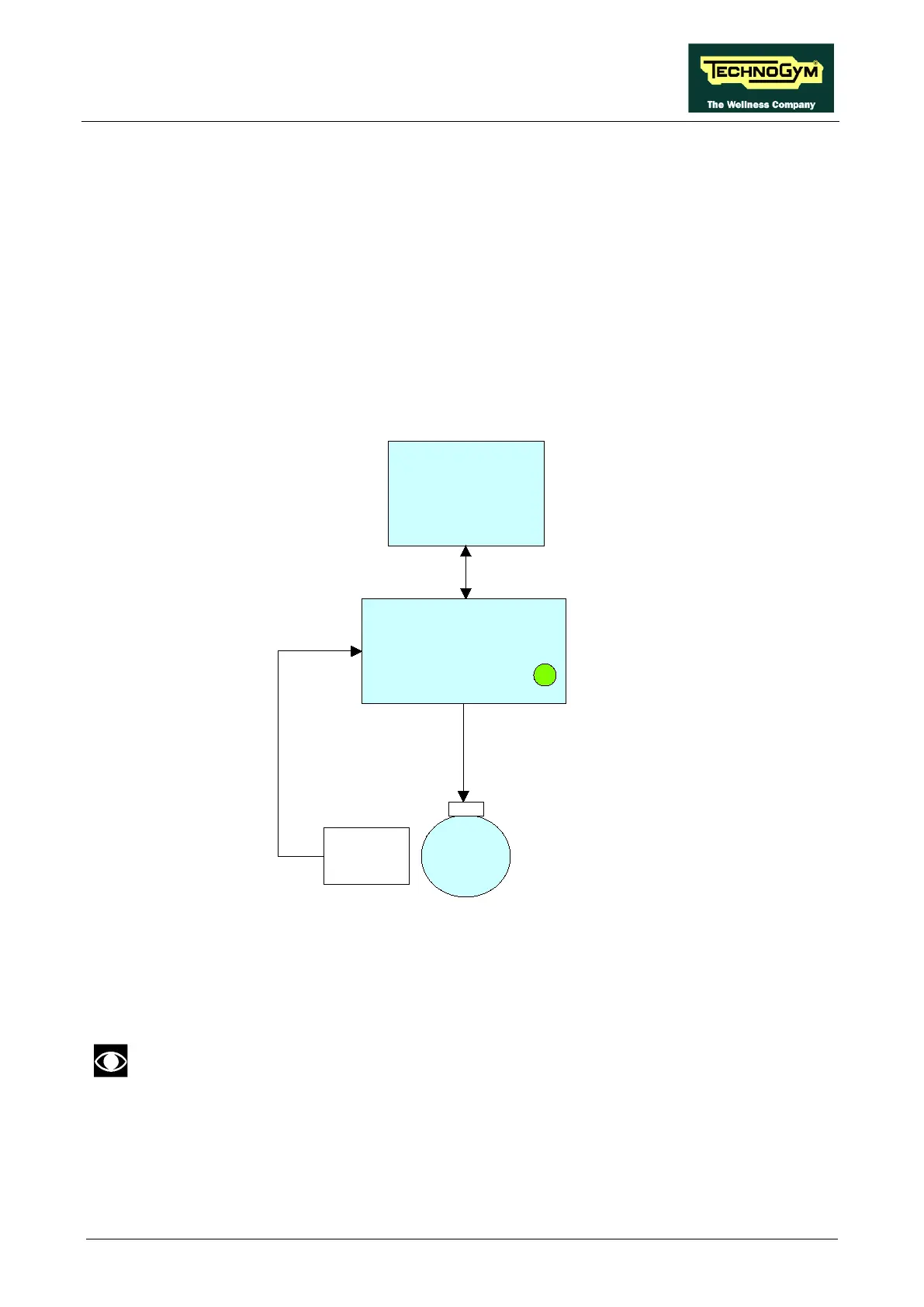
The control block diagram is as follows:
ARM/CPU
BOARD
BRAKE
BOARD
BRAKE
Excitation current
RS-485
CN18/CN9
CN2
CN4
Speed
Sensor
CN2
Green LED
Pulses
To obtain a given exercise effort level, the display board sends the required value of exercise speed
in rpm per minute to the Brake board via the RS-485 serial link. Based on the commands received
the brake board will then apply the appropriate excitation current to the brake winding, which
generates an electromagnetic field.
When the brake interface board receives the signal to generate resistance, the green
LED illuminates.