SYNCHRO Excite +: Service & maintenance manual - rev. 7.1
Page 3.17
3.12.3. THE SIGNALS INVOLVED
The machine uses the following control signals:
• RS-485 Signal
This is a digital signal exchanged between the Brake Board and the Display Board. There is no
provision for monitoring its state.
• Excitation current
This is the current generated by the Brake Board (pins 1-2 of connector CN2) which supplies
the brake winding. The current supplied is a function of the adjustment algorithm.
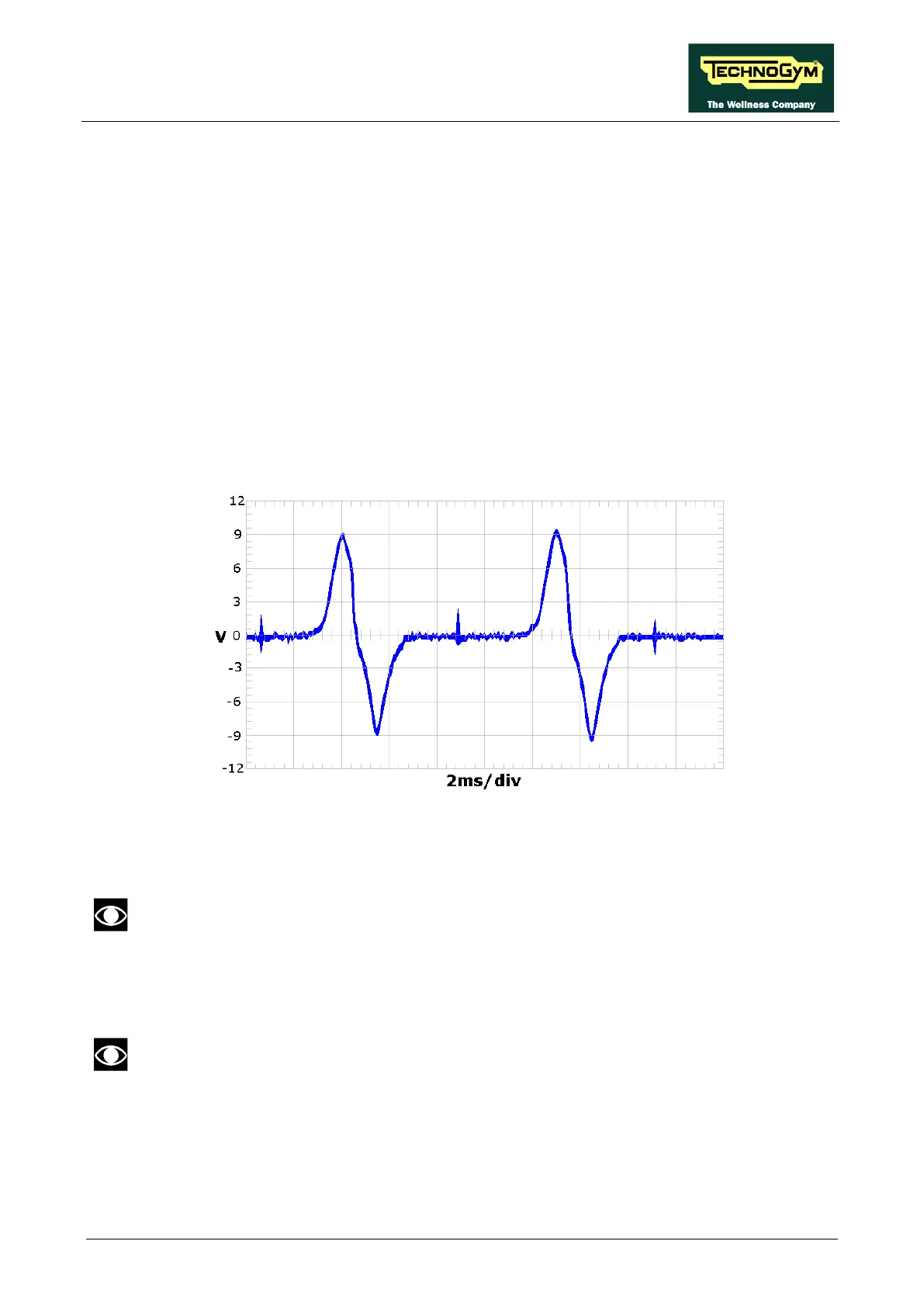
• Pulses
This is the signal produced by the speed sensor, and has the waveform shown in the figure
below:
Figure 3.12-1
The signal enters the Brake Board (pins 3-4 on connector CN2), where it is used to determine
the speed value (RPM)that is sent to the Display Board via the RS-485 serial link.
This signal can also be measured qualitatively using a multimeter. The voltage
measured across the sensor terminals should be 0Vdc when the machine is stopped,
and should increase to a few hundred mV during pedal movement: the higher the
speed, the higher the measured voltage.
Since on the SP models the speed is calculated on the VAC generated by the
alternator, it’s not possible to measure or monitoring this signal using a multi meter.