SYNCHRO Excite +: Service & maintenance manual - rev. 7.1
Page 7.33
Figure 7.8-4
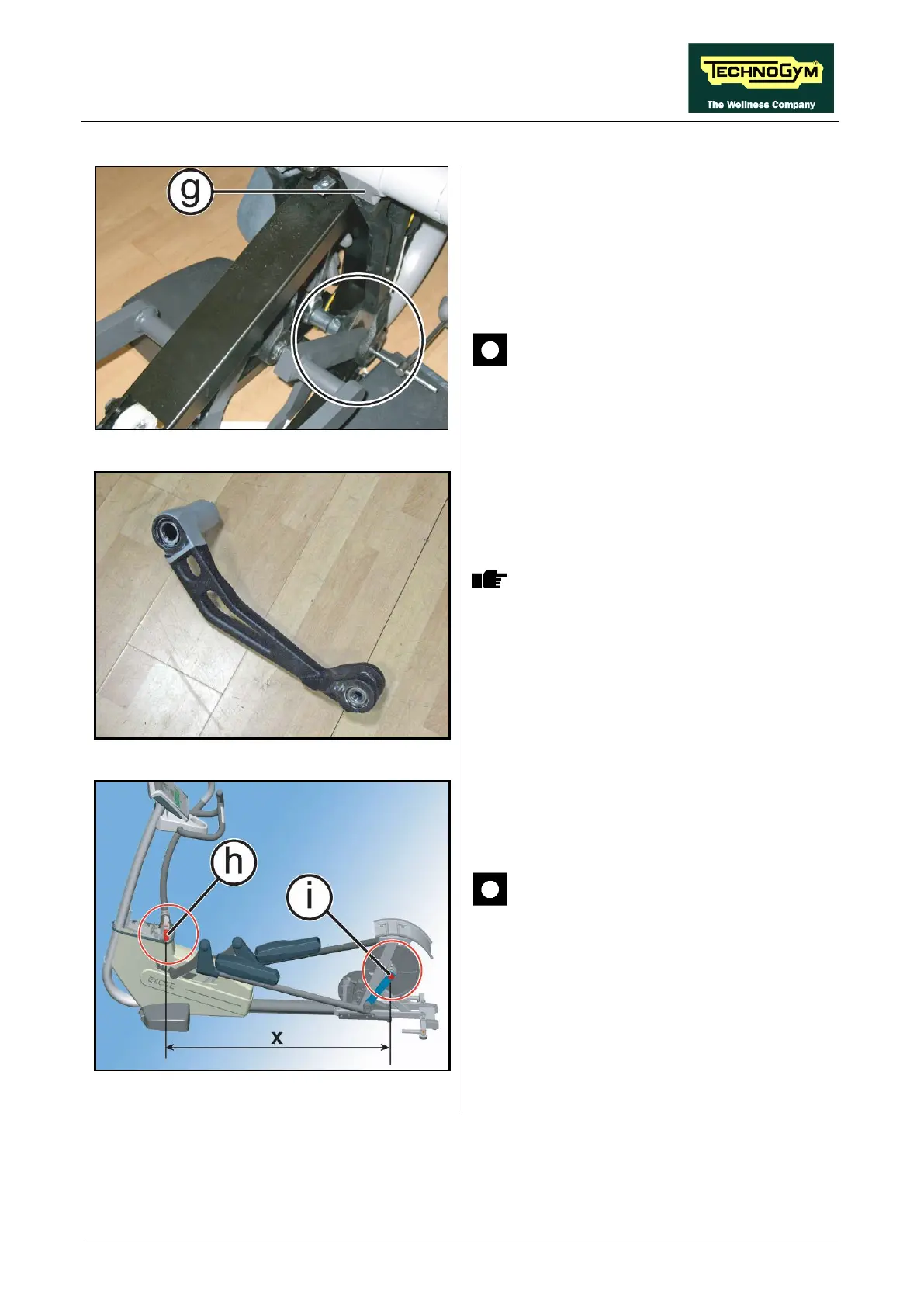
7. Remove the lever (g)
since the constraint
shown in Figure, using a 6mm hexagonal
wrench and
look the opposite ring nut with a
25mm ring nut spanner and a Ratchet
wrench.
ATTENTION: During reassembly
lock down the ring using a torque
wrench setting of 44Nm.
Figure 7.8-5
The bearings are press assembled and
lock with a Seeger
To reassemble the lever, carry out the above
steps in reverse order.
Figure 7.8-6
CAUTION:
remove the pin (h): d
reassembly take care that the “X”
measure, between the fulcrum of (h)
and (i),
is the same on the both side so
to guaranty the lever parallelism.