Components
56
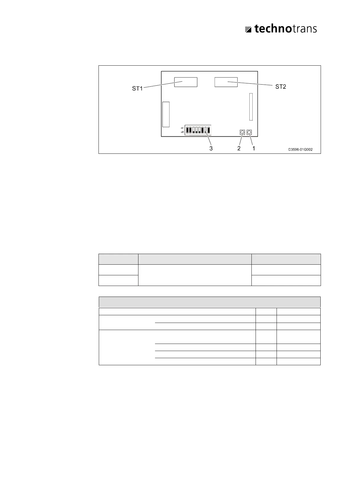
5.12.2 Interface card for basic electronic system (CAN SUB-print)
Fig. 21: CAN-SUB-Print
1 Processor pilot LED
• LED flashes = state of operation
• LED off = processor fault
2 Data communication LED
• LED on = communication fault, interruption of data communication
(CAN-bus)
3 DIP-switch for addressing the CAN mode
Connector Description Connection
ST1 Connection of CAN interface RJ45 (socket)
ST2 RJ45 (socket)
DIP switches CAN setting
DIP1 - 5 Address
DIP6 technotrans standard protocol 0
CANopen protocol 1
DIP7 - 8 baud rate:
DIP7=0, DIP8=0 kBit 125
DIP7=1, DIP8=0 kBit 250
DIP7=0, DIP8=1 kBit 500
DIP7=1, DIP8=1 MBit 1


 To Next Page