7
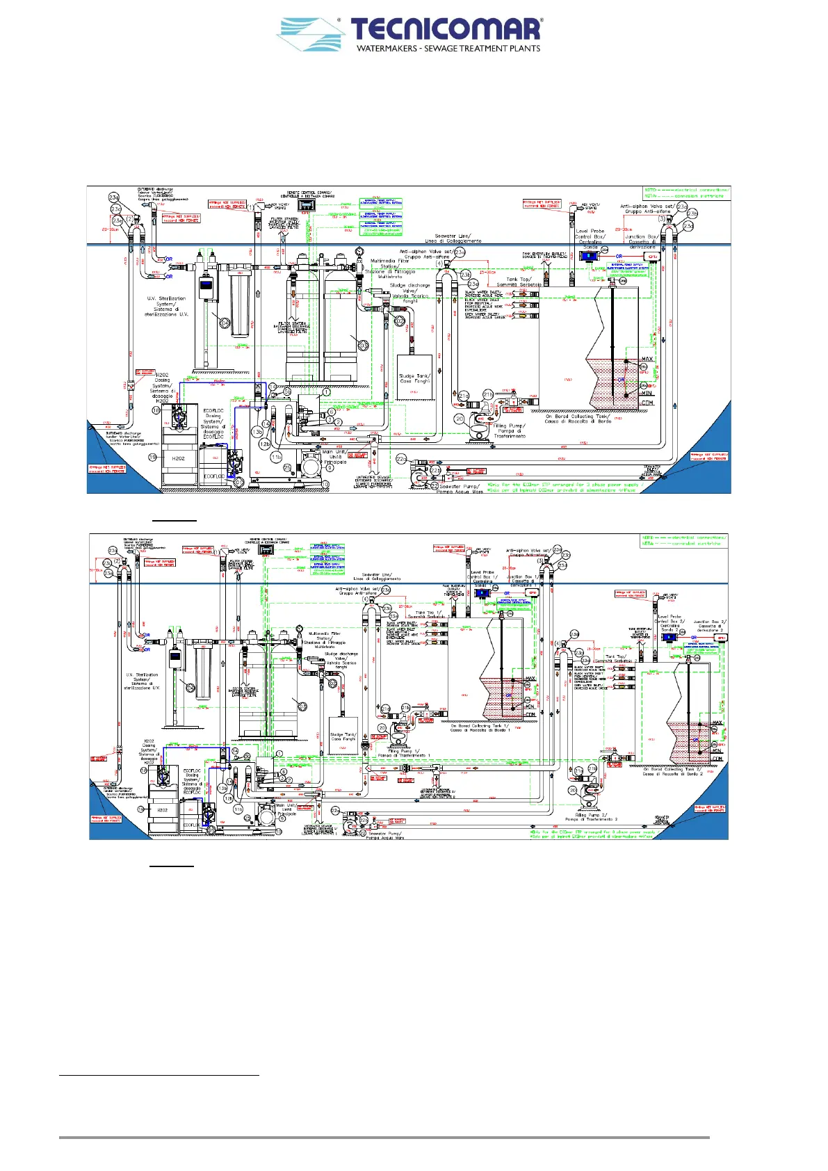
6 SYSTEM DESCRIPTION
The ECOmar S STP can be supplied with two different configuration: 1 Tank Control or 2 Tanks Control.
The main differences between the two configurations are the number of the supplied filling pumps (1 or 2); the number of the
supplied anti-syphon valve set; the number of the supplied level probes; the number of the supplied level probe control boxes;
the dosing systems arrangement and the main control box arrangement.
The diagrams below show a functional installation scheme of the plant with its main components for both configurations.
Fig. 6-1 - Functional installation scheme – 1 Tank Control - (see also annexed drawing)
Fig. 6-2 - Functional installation scheme – 2 Tanks Control - (see also annexed drawing)
As shown in the diagrams above, the system is composed by:
1. A Main Unit Skid made by:
1.1. A tank (Treatment Tank) made of PP (polypropylene) or SS (stainless steel)
*
, where the sewage water is treated;
1.2. A pump (Macerator or Macerating Pump) to treat and discharge the treated water;
1.3. A motorized Discharge Valve (V1) to divert the treated water to the sludge discharge valve (V2) inlet or back to the
treatment tank;
1.4. Level probes
†
, installed on the treatment tank, for the tank level monitoring;
1.5. A pressure sensor (Pressure Switch)
‡
to protect the treatment tank from overpressure;
1.6. A PCB control panel (Main Control Box) with motor protections, contactors, microprocessor, touch pad and liquid
crystal back-lighted display.
*
For the ECOmar 70 S and 145 S; the treatment tank is available only in SS (stainless steel).
†
Nr.1 Multi-point Ball Level Switch for ECOmar 20 S – 32 S – 45 S – 70 S – 145 S.
‡
Only for the STP supplied with the treatment tank in PP (polypropylene).
 Loading...