IST-2194.KM01.01 Istruzione / User’s Manual / Manuel d’utilisation Pag.1/9
(IST-2194.KM01.01_SE194K (30.08.2017).docx)
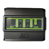
Centralina gas per centrale termica per 3 rilevatori remoti
Gas control unit for heating plants up to 3 remote detectors
Centrale détection de gaz pour chaufferies avec 3 sondes extérieure
TECNOCONTROL S.r.l. - Via Miglioli, 47 20090 SEGRATE (MI) ITALY Tel. +39 02 26922890 - Fax +39 02 2133734
http: www.tecnocontrol.it e-mail: info@tecnocontrol.it
SE194K
Rilevatori collegabili all’SE194K
Detectors which can be connected to the SE194K
Sondes raccordables au SE194K
Modello
Model/ Modéle
Caratteristiche
Features/ Caractéristiques
SE192KM Metano/Methane – IP44
SE192KG GPL/LPG – IP44
SE193KM
Metano/Methane - II 2G Ex d IIC T6 Gb
SE193KG
GPL/LPG - II 2G Ex d IIC T6 Gb
SE183KM
Metano/Methane - II 2G Ex d IIC T5 Gb
SE183KG
GPL/LPG - II 2G Ex d IIC T5 Gb
Leggere Attentamente e Conservare sia questa Istruzione, sia quelle riguardanti i Rilevatori installati.
Please read and keep care of this manual and the manual of installed sensors too.
Lire attentivement et conserver ces instructions, ainsi que celles des sondes installées
Caratteristiche tecniche / Technical specifications / Caractéristiques techniques
Alimentazione principale / Main power supply / Alimentation principale.
110÷240Vac (-15/+10%) 50÷60Hz / 6VA
Alimentazione ausiliaria / Auxiliary power supply / Alimentation auxiliaire.
24VDC (-10/+15%) / 9W
Rilevatore remoto / Remote detector / Sonde extérieure Catalitico / Catalityc / Catalytiques
Ingressi / Inputs / Entrées Max 3 / 4÷20mA
Campo di misura / Standard Range / Champ de mesure 0 ÷ 20% LIE / LEL
1° Soglia di allarme / 1
Alarm threshold / 1
seuil d'alarme 10 o/or/ou 15 % LIE / LEL
2° Soglia di allarme / 2
Alarm threshold / 2
seuil d'alarme 20% LIE / LEL
Contatti relè / Contacts rating / Contact relais 230Vac 3A SPDT
Temperatura-Umidità di funzionamento
Operation Temp-Humidity / Temp. et humidité de fonctionnement
-10 ÷ +50 °C / 5 ÷ 90 % RH
non condensata / non condensed / non condensée
Pressione di funzionamento
Operation Pressure / Pression de fonctionnement
Atmosferica ±10%
Atmospheric±10% / Atmosphérique ±10%
Temperatura-Umidità di immagazzinamento
Storage Temp-Humidity / Temp. et humidité de stockage
-25 ÷ +55°C / 5 ÷ 95 % RH
non condensata / non condensed / non condensée
Grado di protezione / IP Code / Indice de protection IP65
Dimensioni / Size / Dimensions
202 x 153 x 104 mm
Peso / Size- Weight
0,5 Kg
IT
DESCRIZIONE ........................................................................................................................... 2
FUNZIONAMENTO ................................................................................................................................. 2
INSTALLAZIONE .................................................................................................................................... 2
AVVERTENZE ........................................................................................................................................ 3
VERIFICA FUNZIONAMENTO ............................................................................................................... 3
EN
DESCRIPTION ........................................................................................................................... 4
OPERATIONAL DESCRIPTION ............................................................................................................. 4
INSTALLATION ...................................................................................................................................... 4
WARNING ............................................................................................................................................... 5
FUNCTIONAL TESTING ......................................................................................................................... 5
FR
DESCRIPTION ........................................................................................................................... 6
FONCTIONNEMENT............................................................................................................................... 6
INSTALLATION ...................................................................................................................................... 7
AVVERTISSEMENT................................................................................................................................ 7
VERIFICATIONS PERIODIQUES ........................................................................................................... 8