IST-2194.KM01.01 Istruzione / User’s Manual / Manuel d’utilisation Pag.4/9
TECNOCONTROL S.r.l. Via Miglioli 47 SEGRATE (MI) Tel: 02/26 92 28 90 Fax: 02/21 33 734
Verifica funzionamento elettrico della centralina, tenere premuto il pulsante TEST per 5 secondi, si avvierà la
procedura di test, in sequenza si accenderanno tutti i Led dal giallo al 4°rosso e si attiveranno il relè FAULT in cori-
spondenza del Led Giallo , il relè ALARM 1 con il 3° Led rosso e il relè ALARM 2 con il Led ALARM. Poi dopo 5 se-
condi la centralina torna automaticamente in funzionamento normale.
NOTE: la funzione si attiva su tutti i canali anche se disabilitati o con Fault e/o 1° e/o 2° Led Rosso accesi. Ma non
è utilizzabile se uno o più ingressi sono oltre il 10%LEL (3° e/o 4° Led accesi).
EN
DESCRIPTION
The SE194K is a control unit for heating plants or environments to be protected from possible gas leaks, which can be
connected up to 3 remote catalytic detectors for flammable gases. It can be connected to the following detectors:
•
The SE192KM and SE193KM or SE182KM should be used in plants using Methane.
•
The SE192KG and Se193KG or SE182KG should be used in plants using LPG.
The SE194K is for wall mounting and the protection code is IP65. It is mains powered at 110÷240VAC / 50÷60Hz
but can also be connected either to an external 24VDC power supply (e.g. power supply unit with two 12V-7A/h
buffer batteries, our mod. PS180/24VDC).
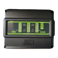
On the front plate, there are three vertical Led bars that indicate the operating status and gas concentration detect-
ed by each remote detector and two function keys (TEST e RESET).
The control unit has two alarm levels with sealed relay outputs (ALARM1 e ALARM2), with tension free changeover
contacts. Furthermore, it is also present another output relay (FAULT) in positive safety for fault situations, and an
auxiliary input (AUX), configurable as an input to connect NO contact devices such as a manual Button or as a con-
trol input for our Manual NC Resetting Valve with positioning sensor.
In Fig.1 a connection example with 3 remote gas detectors, siren, manual reset solenoid valve and manual button.
OPERATIONAL DESCRIPTION
Preheating: when the control unit is powered, the 60 seconds preheating phase begins. This is only for the enabled
inputs (remote detector installed), on the corresponding Led Bar, the yellow LED flashes and at the end of the pre-
heating, the green LED "ON" lights up.
Normal operating: the control unit reads the gas concentration through the remote gas detectors of the enabled
inputs and displays the status on the corresponding Led Bar.
The Green LED lights up to indicate the normal operation and the presence of power
1
st
Red LED: lights up if the gas concentration exceeds 4% LEL.
2
nd
Red LED: lights up if the gas concentration exceeds 8% LIE.
3
nd
Red LED (ALARM 1): lights up if the gas concentration exceeds the 1
st
alarm threshold (configurable to 10 or
15% LEL) and within 5 secondsthe ALARM 1 relay will activate. This relay is normally used as a prealarm using a si-
ren (Our model SE301A when powered by 230VAC or the model SE301B when powered by 24VDC).
4
st
Red LED (ALARM 2): lights up if the gas concentration exceeds the 2
nd
alarm threshold (20% LEL); if the gas
persists, after 30 seconds, the red LED ALARM 2 lights up and the ALARM 2 relay will activate. It is configurable in
positive (normally excited) or negative logic. It is normally used to stop the gas through the manual reset solenoid
valve and/or the interruption of the electrical power at the plant only, the control unit must remain powered.
If the manual button is connected to the AUX input, when pressed, the ALARM 2 relay will be activated.
If it has been installed a manual reset solenoid valve N.C. with magnetic sensor (mod. VR420÷VR480) connected to “AUX” input, in the
case that the gas is still open, the yellow LED and the FAULT Relay will activate (see FAULTS section).
“RESET” Key: this key has two functions:
SILENCING : when the key is pressed, the 3
rd
Red LED on the alarm channel flashes and the ALARM 1 relay con-
nected to the Siren is silenced, but after 120 seconds, it will automatically reactivate.
RESET: if the 2
nd
alarm threshold is exceeded, the ALARM 2 relay and the channel LED bar in alarm remains acti-
vated (latched), even if the gas concentration decreases (because the mounted valve is closed, if installed). After
having eliminated the cause of the alarm, to restore the normal working conditions press the RESET key. For safe-
ty, the key cannot operate when the remote detector is detecting gas.
Faults: The control unit indicates a fault condition of a remote gas detector, with the yellow LED on the correspond-
ing channel and the FAULT relay will activate. This relay is normally energized with voltage-free changeover con-
tacts, if necessary, it can be used both to signal remotely an occurred damage and to signal the absence of power
to the instrument. Fault signals must not be connected to the alarm signals.
Manual reset solenoid valve NC with magnetic sensor failure: this situation appears ONLY when is installed an electro
valve with magnetic sensor; if it not close the gas, (with the ALARM 2 relay in alarm), the magnetic sensor signals to the control unit the mal-
function. In this case all LED will be lighted and relays will be activated. The failure condition (yellow led lighted and FAULT relay activated)
will be cancelled if pressing the RESET key, the solution of the problem will be visualized.
INSTALLATION
The control unit and detectors should be installed according to the national disposition in force on the matter.
Positioning: The control unit must be installed in an accessible location, easily visible and away from heat sources.
The control unit cannot be installed outdoors.
Please note that for safety, the control unit is to be installed in safe areas where there are present or can form
flammable atmospheres and concentrations exceeding 24 % volume oxygen.
 Loading...