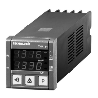
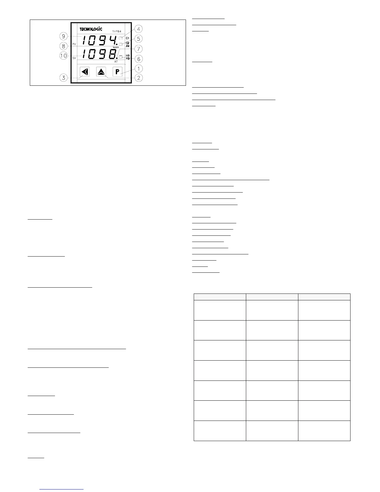
1.1 - FRONT PANEL
1 - Key P : Use to program the functioning parameters and to confirm the
programmed data and pass then to the next parameter.
2 - Key UP: Used to increase the figure on which is placed the "cursor".
(in case of parameters not numerical, "UP" key is needed to select the
available options), to change active set point, to visualize the output
control power, to open manually motorised actuators. Keeping pushed "P"
key and pushing "UP" key, the parameters run over backwards.
3 - Key LEFT : Used to shift the "cursor" (flashing) on the figure that is
desired to modify, to visualise the current measured by TAHB input, to
reset the alarm latch, to close manually motorised actuators.
4 - Led C1 : Signalize when the output C1 is on (on) o r off (off)
5 - Led C2/A4 : Signalize when the output C2/A4 is on (on) or off (off)
6 - Led HB/A3: Signalize when the output HB/A3 is on (on) or off (off)
7 - Led AT: Signalize Seltuning on (on) or Autotuning on (flashing)
8 - Led MAN: Signalize the Manual control (flashing)
9 - Display PV: Normally shows Process Value
10 - Display SV: Normally shows Set Point Value
1.2 - INSTRUMENT CODE
THP 84 a b cc d e f g hh
a = INPUT
T : For temperature probes (Thermcouples, RTD Pt100) or mV signals
(0...50 mV)
I : Normalized Signals 0/4...20 mA
V : Normalized Signals 0/1...5 V
W : Normalized Signals 0/2...10 V
b = OUTPUT C1
R : Relay
O : 24 VDC output for SSR driving
C : Analogue 0/4...20 mA
V : Analogue 0/2...10 V
cc = SECONDARY OUTPU
T
- - : Not present
R - : Relay control output (C2) or alarm output (A4)
O - : 24 VDC output for SSR driving control output (C2) or alarm output
(A4)
C - : Analogue 0/4...20 mA control output (C2)
V - : Analogue 0/2...10 V control output (C2)
- R : Relay alarm (A3) or Heater Break alarm (HB) output
- O : 24 VDC output for SSR driving alarm (A3) or Heater Break alarm
(HB) output
d =
MOTORISED ACTUATORS CONTROL
M : Motorised actuator control present (C1 and C2 relay outputs)
- : Motorised actuator control not present
e =
COMUNICATION INTERFACE
S : RS 485 Serial Interface (only with 16 pins screw terminal block)
I : Auxiliary digital inputs (only with 16 pins screw terminal block)
- : Interface not present
f = SUPPLY
L : 24 VAC/VDC
H : 90 ... 240 VAC
g = CONNECTIONS
F : Faston
V : Screw terminal block
hh
= SPECIAL CODES
2 - TECHNICAL DATA
ELECTRICAL DATA
Supply:
24 VAC/VDC, 90 ... 240 VAC +/- 10%
Frequency AC:
50/60 Hz
Power consumption:
8 VA approx.
Input/s:
1 input for temperature probes (tc B,E,J,K,L,N,R,S,T,U; RTD
Pt100 IEC, Pt100 JIS, or mV signals) or normalized signals 0/4...20 mA,
0/1...5 V, 0/2...10 V. 2 optoinsulated digital inputs for free voltage contacts
or open collectors. 1 input for current transformer with K = 1/0,002 (Max.
200 mA)
Output/s:
Up to 2 outputs. Relay (5 A-AC1, 2 A-AC3 / 250 VAC) ; or
voltage for SSR drive (24VDC/0mA, 14VDC/20mA) or (for C1, C2)
analogue with normalized signals 0/4...20 mA (R load < 600
Ω
), 0/2...10 V
(R load > 100K
Ω
)
Auxiliary supply output:
18 VDC / 25 mA Max (only for norm. sign..)
Electrical life for relay output
: 100000 operat.
Protection class against electric shock:
Class II for Front panel
Insulation:
Reinforced insulation between the low voltage section (supply
and relay outputs) and the front panel; Basic insulation between the low
voltage section (supply and relay outputs) and the extra low voltage section
(inpus, outputs for SSR, analogue outputs); No insulation between inputs,
outputs for SSR and analogue outputs. RS485 optoinsulated
MECHANICAL DATA
Housing:
Self-extinguishing plastic, UL 94 V0
Dimensions:
48 x 48 mm DIN, depht 107 mm (conn. faston), 112 mm
(conn. screw 10 pins), 130 mm (conn. screw 16 pins).
Weight:
200 g approx.
Mounting:
Flush in panel in 45,5 x 45,5 mm hole
Connections:
6.3 mm Faston terminals or screw terminal block 2,5 mm
2
Degree of protection of front panel : IP 54 mounted in panel with gasket
Pollution situation:
Normal
Operating temperature:
0 ... 55 °C
Operating humidity:
30 ... 95 RH% without condesation
Storage temperature:
-10 ... +60 °C
FUNCTIONAL DATA
Control:
ON/OFF, PID
Measurement range:
according to the used probe (see range table)
Display resolution:
according to the probe used 1/0,1/0,01/0,001
Overall accuracy:
+/- 0,15 % fs (input T), +/- 0,05 % fs (inputs I, V, W)
Sampling rate:
5 samples per second
Serial Interface :
RS485 optoinsulated
Communication protocol:
MODBUS RTU (JBUS)
Baud rate:
Programmable from 300 ... 9600 baud
Action:
1C type according to EN 60730-1
Compliance:
ECC directive EMC 89/336 (EN 50081-1, EN 50082-1), ECC
directive LV 73/23 and 93/68 (EN 60730-1)
MEASUREMENT RANGE TABLE
-99.9 ... 400.0 °C
-99.9 ... 752.0 °F
-99.9 ... 320.0 °R
-270 ... 400 °C
-454 ... 752 °F
-216 ... 320 °R
tc T
(t)
-50.0 ... 999.9 °C
-58.0 ... 999.9 °F
-40.0 ... 999.9 °R
-50 ... 1760 °C
-58 ... 3200 °F
-40 ... 1408 °R
tc R (r)
tc S (S)
-99.9... 999.9 °C
-99.9 ... 999.9 °F
-80.0 ... 999.9 °R
-100... 1300 °C
-148 ... 2372 °F
-80 ... 1040 °R
tc N
(n)
-99.9 ... 999.9 °C
-99.9 ... 999.9 °F
-99.9 ... 999.9 °R
-200 ... 1370 °C
-328 ... 2498 °F
-160 ... 1096 °R
tc K
(CrAl)
-99.9 ... 950.0 °C
-99.9 ... 999.9 °F
-99.9 ... 760.0 °R
-200 ... 950 °C
-328 ... 1742 °F
-160 ... 760 °R
tc J
(J)
-99.9 ... 700.0 °C
-99.9 ... 999.9 °F
-99.9 ... 560.0 °R
-150 ... 700 °C
-238 ... 1292 °F
-120 ... 560 °R
tc E
(E)
400.0 ... 999.9 °C
752.0 ... 999.9 °F
320.0 ... 999.9 °R
400 ... 1820 °C
752 ... 3308 °F
320 ... 1456 °R
tc B
(b)
4 DIGIT with D.P.4 DIGIT PROBE
TECNOLOGIC - THP 84 USER MANUAL (I - GB) - Vr. 02 - ISTR 00132 - PAG. 12
 Loading...