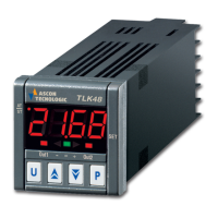
a positive differential switching point for direct controls (ex.Cooling
processes). Furtheremore the two Sets can be programmed independently
or dependently throught the parameter Sets Connection ("OCO"), and in
the case of set dependentlythe real regulation Set of output 2 will be
[Set1+Set2]. If output 2 is used as an alarm output, par. "OCO"
determines if the alarm is absolute or relative (in=absolute, di=relative)
and par. "HC2" determines if the alarm is low or high (H=low, C=high).
The operating mode can be also modified by means of outputs delay
parameter (par. "od") or Dynamic Set Point function, see the next
chapters for these functions.
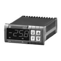
4.2 - NEUTRAL ZONE CONTROL
The Neutral Zone control mode concerns both outputs and is generally
necessary for controllig a plant that possesses an Positive regulation
element (ex. Heating, Humidification etc.) and a Negative regulation
element (ex. Cooling, Dehumidification etc.) . The functioning is
determined by the Set1 (Set2 is automatically disconnected) and Neutral
Zone (par. "db"). Subsequently the regulator operates as follows: switches
off the outputs when the process value is the same as Set, switch on the
output OUT1 when the process value is under as [Set1-db], and switch on
the output OUT2 when the process value is upper as [Set1+db]. Thus the
Positive regulation element will be connected to output OUT1, while the
Negative regulation element is at output OUT2.
4.3 - PID CONTROL AND AUTOTUNING FUNCTION
PID control mode can only be carried out through output OUT 1 while
output OUT 2 can only operates by means of ON/OFF control mode with
Set 2 independent or dependended in respect with Set 1 and can therefore
be used as an alarm (see ON/OFF regulator). The PID algorithm of the
instrument is provided to program the following parameters:
For
PROPORTIONAL term :
"Pb" - Proportional Band,
"rst" - Manual reset
"Ct" - Cycle time.
For
INTEGRAL term:
"It" - Integral time
For
DERIVATIVE term:
"dt" - Derivative time
The instrument is set on parameters relative to PID control of standard
value. If ever these should result to be unsuitable it would be advisable to
program the AUTOTUNING function. The Autotuning function permits the
automatic tuning of the PID instrument parameters.
To active the AUTOTUNING function proceed as follows :
- Set the desired "Set point".
- Set the desired parameters and especially "HC1".
- Set the parameter "Ft": Pi
- Connect the instrument with the plant
- Set the parameter "tun" : y
- Wait for the outing from the programmation
Now, the Autotuning function is activated and it's shown by the flashing of
the process value on the display. The regulator automatically tunes all the
right parameters for a correct PID control mode. Before to switch off the
instrument always wait for the end of the Autotuning process, indicated by
the return of the display on the normal functioning, . The Autotuning
procedure has been limited at a maximum time of 4 hours, after this time, if
the Autotuning is not completed the instrument automatically get out from
the procedure, showing constantly on the display the "EEE" indication. To
stop the Autotuning cycle or re-establish the normal functioning after an
error, switch off and on the instrument. The calculated values will be
automatically memorised by the instrument at the end of the Autotuning
cycle, in the PID control parameters.
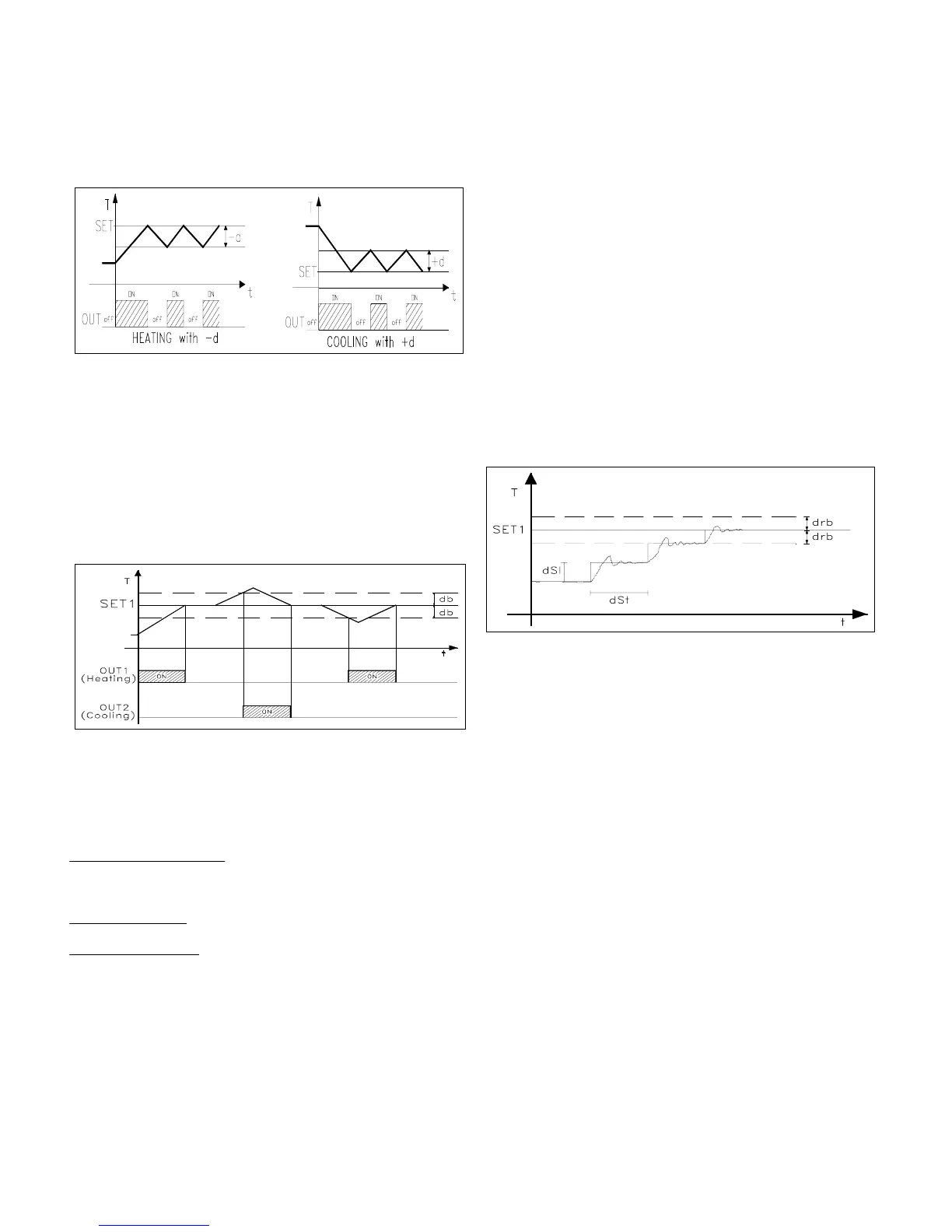
4.4 - DYNAMIC SET POINT FUNCTION
This function is only obtainable throught output OUT 1 and is usefull to
avoid starting over-extention of the process value caused by the inertness
of the system or when is wished a gradual reaching of Set value. Infact by
means of this function an automatic increase in the time of the regulation
Set from the power on-process value to the programmed Set is obtained.
The parameters to be programmed for this function are:
"drb" : Symmetrical semi-band over-lapping the Set outside from which
the function is activated.
"dSI" : Increment value of dynamic Set between two successive increments
of the dynamic Set value.
"dSt" : Time lapse between two successive increments of the dynamic Set
value.
The Dynamic Set Point function is automatically disconnected by setting
dSi = 0.
5 - PROGRAMMING
5.1 - PROGRAMMING OF SET-POINTS
Press key P then release it, led OUT1 will flash and the SET1 value will be
shown on display. To modify press key UP so as to increase value or
DOWN so as to decrease it. These keys count one digit at a time but if the
keys are pressed for over one second the value increases or decreases fast
and after two seconds the speed increases even more, so as to reach the
desired value immediately. Pressing key P again and releasing it, led
OUT2 will flash and SET2 which was previously set, will be displayed, it
can be modified by pressing keys UP or DOWN as already mentioned. The
outgoing from the Set programming mode occurs automatically by not
pressing any key for about 5 seconds, thus the process value will again be
displayed.
5.2 - PROGRAMMING OF PARAMETERS
To accede to the operating parameters it is necessary to press key P
holding it down for about 5 seconds, afterwhich the led OUT1 will flash
and the code of the first parameter will be visualized on the display. At this
point key P can be released and by pressing UP or DOWN the desired
parameter can be selected. Once the parameter on which we intended to
operate has been selected to modify it press P, while holding it down, the
set of the parameter will show up. To modify this value keep P pressed
while acting on UP or on DOWN so as to increase or decrease the value.
Once the desired value has been set release P and the selected parameter
code can be read on the display. By pressing UP or DOWN it is therefore
possible to choose another one and modify it as previously mentioned. To
outgoing from the programming mode no key is to be pressed for about 20
seconds, the instrument will automatically return to normal functioning
mode, visualizing the process value.
TECNOLOGIC - THP 96 USER MANUAL (I - GB) - Vr. 02 - ISTR 00997 - PAG. 7
 Loading...