48
Instruction and maintenance manual
ENGLISH
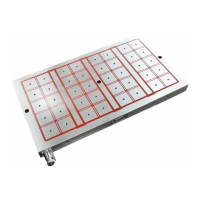
3.2 Main principles concerning the
clamping of parts
The magnetic force lines close between the northern
and southern pole of the magnetic chuck.
This ow can be used to attract and clamp ferrous
parts. A steel part exposed to a magnetic eld is at-
tracted by the opposed polarity of the eld towards
the magnet, until contact is achieved.
The ow produced by the steel varies according to
the material it contains, its dimensions, the level of
contact achieved between the part to clamp and the
magnetic chuck, and the easiness with which the
ow passes through the steel.
3.3 Factors that influence magnetic
forces
The amount of magnetic ow applied to the part is
the factor that most inuences the clamping force.
To achieve an optimum clamping force, it is neces-
sary to apply the greatest possible magnetic ow
to the part being machined. If the part has a simple
design, it is sufcient to correctly position it on the
northern and southern poles of the magnetic chuck.
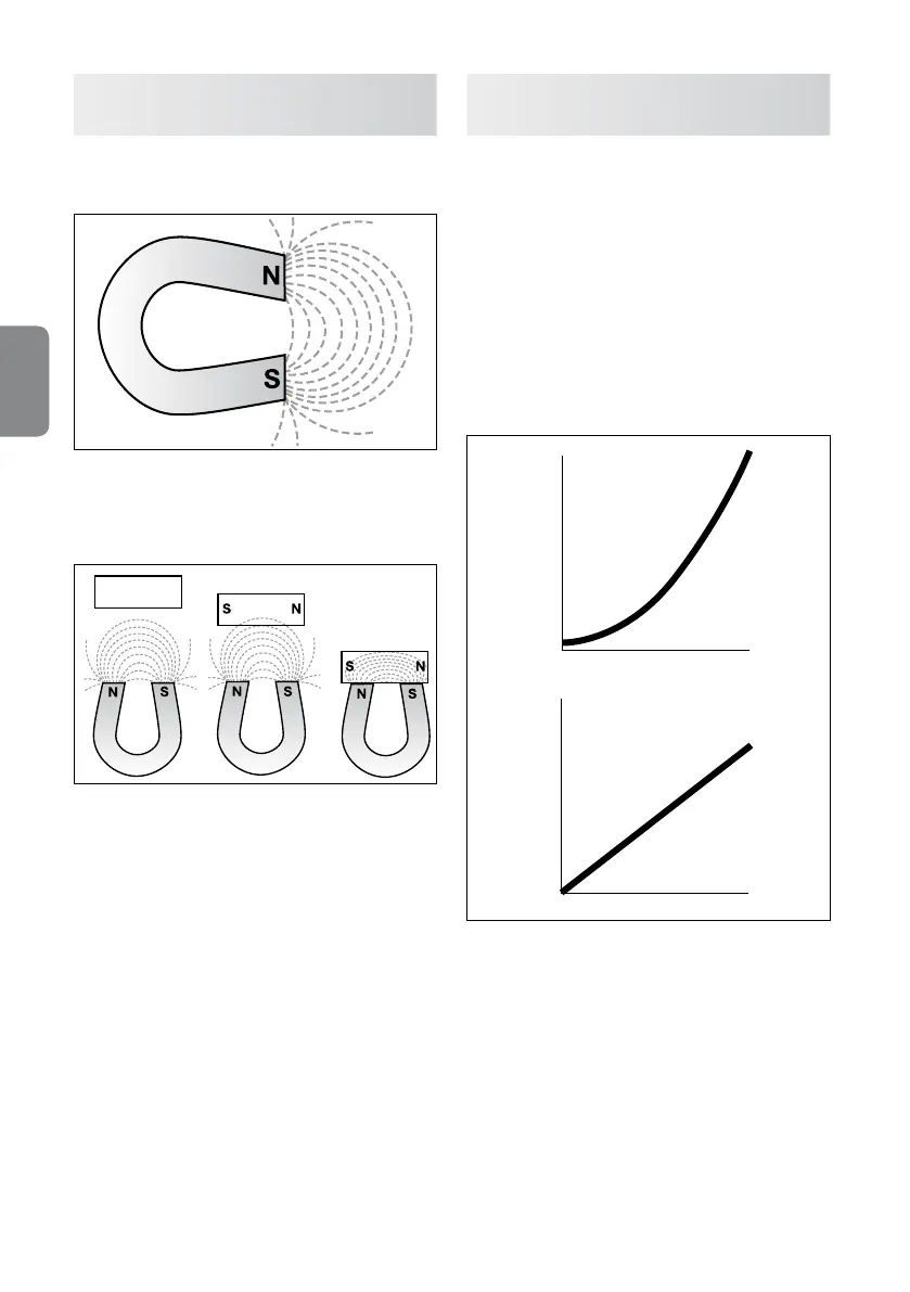
The clamping force is proportional to:
1) The square of the density of the magnetic ow
present on the surface that is in contact with the
part
2) The area of the part that is in contact with the
magnetic chuck up to maximum saturation point.
Clamping force daN/cm
2
Flow density
Surface
Clamping force daN/cm
2
Doubling the contact area means doubling the
clamping force. A 10% reduction in the ow density
reduces by 19% the clamping force. If the ow den-
sity is halved, the clamping force is reduced by 75%.
The ow density tends to reduce when the ow en-
counters a magnetic resistance (reluctance). A typi-
cal example of this type of situation is represented
by air gaps (where an air gap represents the average
contact distance between the part to machine and
the magnetic chuck) and the elements that form the
material of the part being clamped. The main factors
that inuence the ow density and clamping force
applied to a part of any dimension are described
below.