6-35
Communication
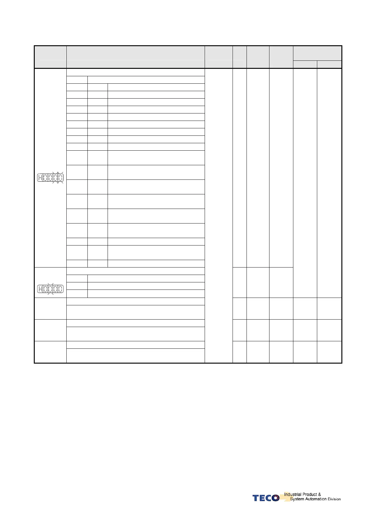
Address
Parameter Name & Function Default Unit
Setting
Range
Control
Mode
RS232 RS485
DO-1 Functions
Setting Explanation
Signal Functions
01
RDY
Servo Ready
02
ALM
Alarm
03
ZS
Zero Speed
04
BI
Brake Signal
05
INS
In Speed
06
INP
In Position
07
HOME
HOME
08
INT
In Torque
09
P1
Position Display 1 for Tool Turret
mode
0A
P2
Position Display 2 for Tool Turret
mode
0B
P3
Position Display 3 for Tool Turret
mode
0C
P4
Position Display 4 for Tool Turret
mode
0D
P5
Position Display 5 for Tool Turret
mode
0E
P6
Position Display 6 for Tool Turret
mode
0F
OL
Motor Over-load Signal
10
BAT
Absolute Encoder Battery Module
Fault Si gnal
★
Hn613.0
Hn613.1
11
LIM
CWL/CCWL Drive Disable Signal
X
01
│
11
ALL
DO-1 Active Level
Setting Explanation
0 Close, when the output is activated.
★
Hn613.2
1 Open, when the output is activated.
X
0
│
1
ALL
C47H 050DH
DO-2
★
Hn614
Please refer to Hn614
X
001
│
111
ALL C48H 050EH
DO-3
★
Hn615
Please refer to Hn614
X
001
│
111
ALL C49H 050FH
DO-4
★
Hn616
Please refer to Hn614
Refer to
the cross
reference
table on
page
5-65
.
X
001
│
111
ALL C4AH 0510H
New setting will become effective after re-cycling the power.
Warning! If any of programmable Inputs of DI-1 ~ DI-13 are set for the same type of function
then the logic state selection ( NO or NC selection) for these inputs must be the same type.
Otherwise an Alarm will be displayed. AL-07 (Abnormal DI/DO programming).