3-11
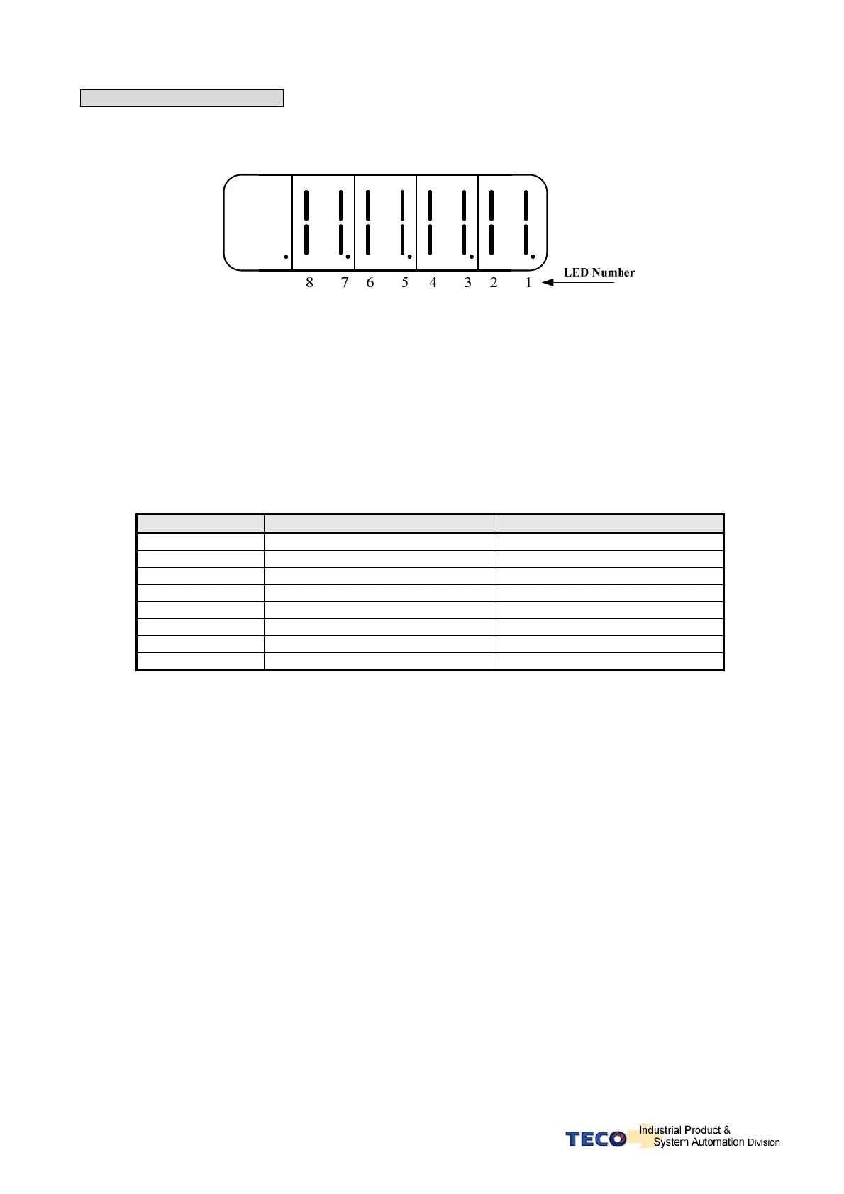
dn-02 (Output terminal status)
Use dn-02 to check the status of output terminals.
Output status display is described below:
When output terminal signal has a low logic level (close loop with IG24),
the corresponding LED will be on.
When output terminal signal has a high logic level (open loop with IG24),
the corresponding LED will be off.
Table below shows the functions of the digital outputs.
DO-1~DO-4 are programmable outputs. Default settings are shown below.
DO-5~DO-8 are fix function outputs. ( non-programmable)
For programmable output list see section 5-6-1.
LED No. Output terminal number Default function
1 DO-1
RDY
2 DO-2
ALM
3 DO-3
ZS
4 DO-4
INP
5 DO-5
LM/A0
6 DO-6
PC/A1
7 DO-7
ST/A2
8 DO-8
BB/A3
Note: To set the logic state (High or Low) of for programmable digital outputs refer
to section 5-6-1.
For the DO-5~DO-8 ( non-programmable) terminals are active when logic is low.