47
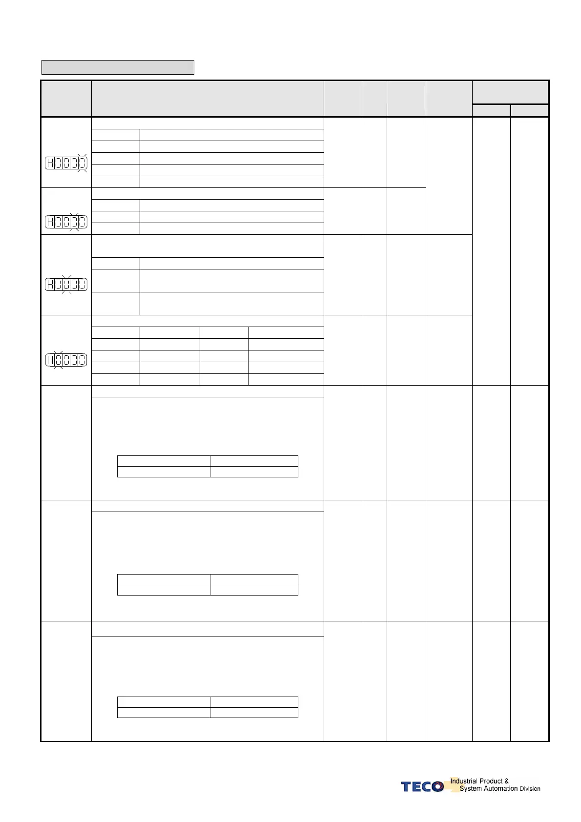
Position Control Parameter
Address
Parameter
Name & Function Default
Unit
Setting
Range
Control
Mode
RS232
RS485
Position pulse command selection
Setting
Explanation
0 (Pulse)+(Sign)
1 (CCW)/(CW) Pulse
2 AB-Phase pulse x 2
★
Pn301.0
3 AB-Phase pulse x 4
0 X
0
│
3
Position- Pulse Command Logic
Setting
Explanation
0 Positive Logic
★
Pn301.1
1 Negative Logic
0 X
0
│
1
Pe
Selection for command receive of drive inhibit
mode
Setting
Explanation
0
When drive inhibits
position command input coherently.
★
Pn301.2
1
When drive inhibit occurs, ignore the value
of position command.
0
X
0
│
1
Pi
Pe
Pulse command filter band width selection
Setting
Explanation
Setting
Explanation
0 850KHz 4 280KHz
1 780KHz 5 140KHz
2 620KHz 6 80KHz
★
Pn301.3
3 440KHz 7 40KHz
3 X
0
│
7
Pe
550H
0301H
Electronic Gear Ratio Numerator 1
Pn302
Use input contacts GN1 & GN2 to select one of four
electronic Gear Ratio Numerators.
To select Numerator 1, the statue of the input-contacts
GN1 & GN2 should be as follows:
Input Contact GN2
Input Contact GN1
0 0
Note: Input contacts status “1” (ON) and “0” (OFF).
Refer to 5-6-1 to set high or low input logic levels.
1 X
1
│
50000
Pi
Pe
560H
0302H
Electronic Gear Ratio Numerator 2
Pn303
Use input contacts GN1 & GN2 to select one of four
electronic Gear Ratio Numerators.
To select Numerator 2, the statue of the input-contacts
GN1 & GN2 should be as follows:
Input Contact GN2
Input Contact GN1
0 1
Note: Input contacts status “1” (ON) and “0” (OFF).
Refer to 5-6-1 to set high or low input logic levels.
1 X
1
│
50000
Pi
Pe
561H
0303H
Electronic Gear Ratio Numerator 3
Pn304
Use input contacts GN1 & GN2 to select one of four
electronic Gear Ratio Numerators.
To select Numerator 3, the statue of the input-contacts
GN1 & GN2 should be as follows:
Input Contact GN2
Input Contact GN1
1 0
Note: Input contacts status “1” (ON) and “0” (OFF).
Refer to 5-6-1 to set high or low input logic levels.
1 X
1
│
50000
Pi
Pe
562H
0304H
 Loading...

