63
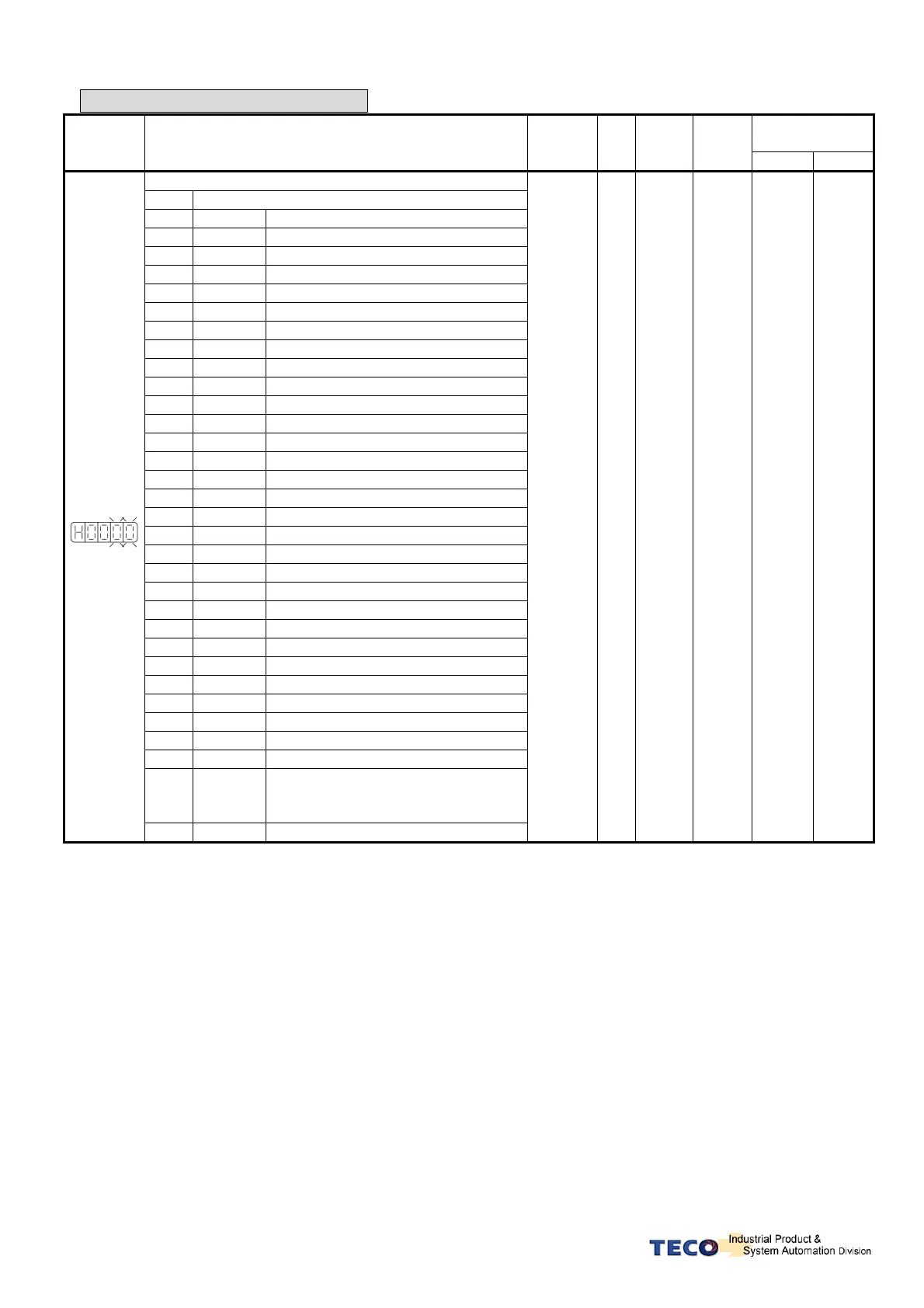
Multi-Function Input Parameters
Communication
Address
Parameter
Name & Function Default
Unit
Setting
Range
Control
Mode
RS232
RS485
DI-1 Function
Seting
Explanation
Signal Functions
01
SON
Servo On
02
ALRS
Alarm Reset
03
PCNT
PI/P Switching
04
CCWL
CCW Limit
05
CWL
CW Limit
06
TLMT
External Torque Limit
07
CLR
Clear Pulse Error Value
08
LOK
Servo Lock
09
EMC
Emergency Stop
0A
SPD1
Speed 1
0B
SPD2
Speed 2
0C
MDC
Control Mode Switch
0D
INH
Position Command Inhibit
0E
SPDINV
Speed Inverse
0F
G-SEL
Gain Select
10
GN1
Electronic Gear Ratio Numerator 1
11
GN2
Electronic Gear Ratio Numerator 2
12
PTRG
Position Trigger
13
PHOLD
Position Hold
14
SHOME
Start Home
15
ORG
Home Position Reference (Origin)
16
POS1
Internal Position select 1
17
POS2
Internal Position select 2
18
POS3
Internal Position select 3
19
POS4
Internal Position select 4
1A
TRQINV
Torque Inverse
1B
RS1
Torque CW Selecting
1C
RS2
Torque CCW Selecting
1D
MDC2
Control mode selection for tool turret
1E
POS5
Internal position command selection
5
(Tool NO. selection 5)
★
Hn601.0
Hn601.1
1F
POS6
Tool NO. selection 6
Refer to
the cross
reference
table on
page 77.
X
01
│
1F
︵
HEX.
︶
ALL C23H
0501H
★
New setting will become effective after re-cycling the power.
Warning! If any of programmable Inputs of DI-1 ~ DI-13 are set for the same type of function
then the logic state selection ( NO or NC selection) for these inputs must be the same type.
Otherwise an Alarm will be displayed. AL-07 (Abnormal DI/DO programming).