Technical equipment of TC600 PLC
73 TXV 138 08.02
t
OH,
t
OL
- output delay
Closing time or opening time of the output switch
- typ. 4 ms for relay outputs
- max. 400 s for transistor outputs
t
OP
- time of the program response (see further text)
t
OA
- time of the programmable controller response (see further text)
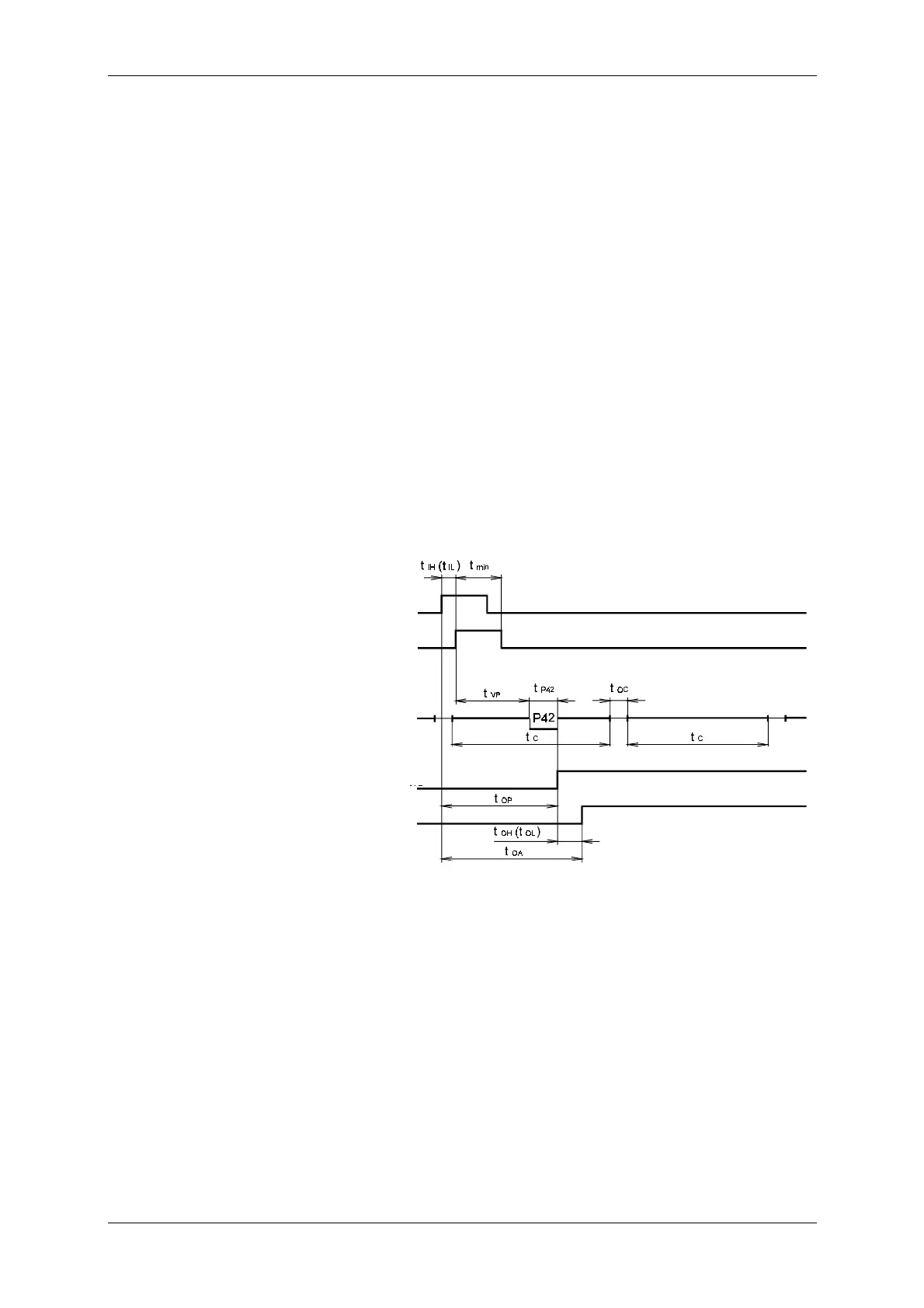
Time diagram in Fig. 10.1 illustrates the shortest possible response time
of the programmable controller t
OA
to change of signal at the interrupt input.
In the P42 process, identification of the interrupt source is performed and
servicing of the interrupt by writing to the output physical address (see item
10.5.12). Allowing of the interrupt from the ascending signal edge is as-
sumed. Response time of the programmable controller is the sum of the
following times:
t
OA
= t
IH
(t
IL
) + t
VP
+ t
P42
+ t
OH
(t
OL
)
It is apparent from the times definition that the user may affect the pro-
grammable controller response by the program structure and by selection of
the output switch type. For example, if the user instruction is placed as the
first or last instruction in the P0 process, in time t
VP
the sum of times t
OC
a
t
USI
may be applied. Exceeding of the allowed time of the interrupt process
(t
P42
5 ms) is evaluated by the diagnostic system as a serious error of the
user program (see Chapter 11).
Cyclicly executed user
program interrupted by
the P42 process
Writing of the program
response to the
memory pad
Signal at the binary
output
Signal at
the interrupt input
Signal after
the input filter
Fig. 10.1 Response time of the programmable controller to change of the
signal at the interrupt input at processing of the response in the
P42 process and writing to the output physical address
Programmable
controller response
asynchronous to the
program cycle


 To Next Page