8
EN
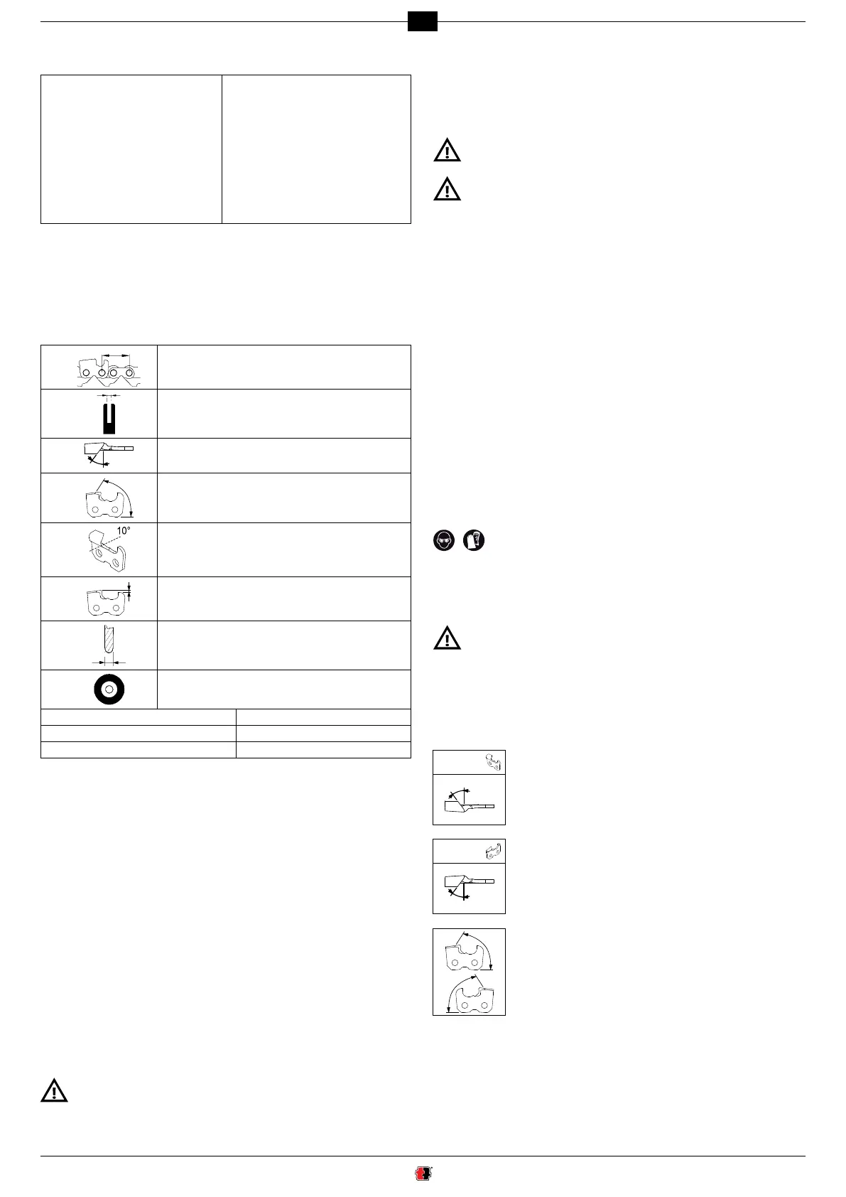
15. CHAIN INFORMATION
The chain must be completely inspected before sharpening it to make sure it is intact.
(g. 8) Cutter parts: (g. 8A) Chain parts:
1 Top part 1 Connection link
2 Top cutting angle 2 Left cutter
3 Side cutting angle 3 Right cutter
4 Sharpening recess 4 Driving link (pulling link)
5 Depth gauge 5 Rivet
6 Bit
7 Heel
8 Rivet hole
16. CHAIN IDENTIFICATION
- Before you start to sharpen, you need to know the type of chain and the relative
adjustment angles. These characteristics are written in the owner’s manual of the
chainsawonwhichthechainisttedoronthechainpack.
- Thechainidenticationcodeisusuallywrittenonthedrivinglink.
- You can also identify the chain using a template or gauge.
- Consult the CHAIN CHART at the end of this manual.
The columns in this chart provide the following information:
A
÷ 2
Chain pitch
B
Driving link width
C
Top sharpening angle (vise rotation)
D
Cutting angle (arm rotation)
E
Down angle (vise inclination)
F
Gauge depth
G
Grinding wheel thickness
H
Grinding wheel code
I Oregon chain codes N Carlton chain codes
L Windsor chain codes O Stihl chain codes
M SARP chain codes P EM chain codes
16.1 INSTRUMENTAL MEASUREMENTS (FIG.9)
a - Measure the gauge depth using the suitable shape.
b - Put the template on this side and measure the chain PITCH.
c - Put the template on this side to measure the cutter length.
d - The driving link width is measured using a suitable instrument (i.e. gauge).
17. GRINDING WHEEL WARNINGS
- Use a grinding wheel suitable for the type of chain to be sharpened; consult the
chain chart at the end of the manual.
- Do not force the grinding wheel on the hub and do not alter the centering hole
diameter.Donotusegrindingwheelsthatdonottperfectlyinplace.
- Useexclusivelycleanandperfectintacthubandangetotthegrindingwheel.
- Makesuretheoutsidediametersofthehubandangeareidentical.
18. FITTING THE GRINDING WHEEL
- Unscrew the screws V10 and remove the guard P10 (g.10).
- RemovethescrewV8andtheangeF8onthehub(g.11)
- Choose the grinding wheel based on the type of chain to be sharpened (column H
in chain chart).
- Insert and perfectly center the grinding wheel in the dedicated seat on the
hub (g.12).
- InserttheangeF8andtightenthescrewV8(g.13).
Make sure you t the ange as illustrated in g.12.
Ifthegrindingwheelisttedwiththeangestootight,itcouldbreakduring
use and put the operator at risk. To avoid such risk, tighten screw M6x25
to 7 Nm (if possible, check with dynamometric spanner).
- Reassemble the guard P10 and tighten the related screws V10 (g.14).
19. CHECKING THE ASSEMBLY OF THE GRINDING WHEEL
- Stand at the side of the grinding wheel, start the grinder and visually make sure
the grinding wheel does not oscillate sideways or crosswise, consequently causing
abnormal vibrations.
- If this should be the case, stop the appliance immediately and check if the grinding
wheelhasbeenttedcorrectly.Ifnecessary,replacethegrindingwheelwithanother
original one.
Alwayscheckafreshlyttedgrindingwheelatworkingspeedforatleastone
minute before you start grinding, standing at a safe distance and making sure
nobody else approaches the appliance.
20. ELECTRICAL CONNECTION
- Make sure the electrical system power supply complies with the values written on
the rating nameplate.
- The power supply voltage must not differ from that written on the nameplate
by ±5%.
- The connection to the electric mains must be prepared subject to current standards
in force in the country in which the appliance is used.
- The power socket used for the appliance must have an earth wire, adequate fuse
and must be protected by a differential circuit breaker with tripping sensitivity no
higher than 30 mA.
21. START-UP
- Plug the power cable into the mains.
21.1 OPERATOR POSITION (FIG.14A)
- The operator must stand in front of the machine and maintain a position that allows
him to grip the arm correctly and adjust the vice.
22. CHECKING THE GRINDING WHEEL SHAPE
- Withtheapplianceturnedoff,checkthegrindingwheelproleusingthededicated
template (g.15);ifnecessary,dressthewheeltorestorethecorrectprole.
23. GRINDING WHEEL DRESSING
Wear personal protection equipment.
- Start the grinder by turning the switch to position “1”.
- Once started, the lamp lights up to illuminate the sharpening area.
- Prolethegrindingwheelwiththedressingbrick,alwaysworkingwithextreme
caution,holdingitrmlyandsecurely(g.16).
- Stoptheapplianceandcheckiftheproleiscorrectusingthetemplate(g.17).
Contact with the grinding wheel while it spins at high speed may cause
burning and abrasions.
24. ADJUSTING THE GRINDER
24.1 SHARPENING ANGLES
- Once you have established the type of chain to be sharpened, look-up the adjust
-
ment angles (vise and arm) in the chain chart (columns C/D/E).
RH
CUTTER
24.2 SETTING THE TOP SHARPENING ANGLE (FIG.18-19)
- Loosen the knob M20.
- Turn the vise clockwise.
- Position the reference mark on the vise by the desired angle.
- Tighten knob M20 again.
LH
CUTTER
24.3 SETTING THE TOP SHARPENING ANGLE (FIG.18-20)
- Loosen the knob M20.
- Turn the vise counter clockwise.
- Position the reference mark on the vise by the desired angle.
- Tighten knob M20 again.
24.4 SETTING THE CUTTING ANGLE (FIG.21-21A)
(right and left cutters)
- Loosen the knob M23 and turn the arm towards the right. Position
the reference mark by the angle desired.
- Tighten knob M23 again.
 Loading...